Multilobe rotary motion asymetric compression/expansion engine

a multi-lobe, asymetric compression technology, applied in the direction of machines/engines, liquid fuel engines, rotary/oscillating piston pump components, etc., can solve the problems of thermodynamic efficiency, asymmetry is typically only obtained at the expense of significantly increased mechanical complexity,

Inactive Publication Date: 2009-08-25
GYROTON CORP
View PDF29 Cites 30 Cited by
  • Summary
  • Abstract
  • Description
  • Claims
  • Application Information

AI Technical Summary

Benefits of technology

[0007]The present invention incorporates an engine case containing a rotor with a plurality of lobes carried by the rotor. The lobes are extendible from a cylindrical surface of the rotor to maintain sealing contact with a contoured wall of the case. The contour incorporates a first portion diverging from a first tangency point between the rotor and case wall and a second portion contracting from a first maximum divergence to a second tangency point between the rotor and case, a third portion diverging from the second tangency point to a second maximum divergence and a fourth portion converging to the first tangency point. The first and second portion define a first volume and the third and fourth portion define a second volume swept by each pair of adjacent lobes. In selected embodiments, the first volume and second volume are asymmetric allowing tailored compression and expansion ratios for operation of the engine. Also in selected embodiments, the case contour incorporates as an element of the second portion an arc concentric with and proximate to the diameter of the rotor while approaching the second tangency point to create a minimum volume and to extend the time of maximum compression to fully initiate combustion prior to expansion. The contour also incorporates a similar element in the region of the termination of the fourth portion and the beginning of the first portion wherein an arc concentric with and proximate to the diameter of the rotor acts as a volume separation between the exhaust and subsequent intake. A combustion air inlet proximate the first tangency point and first portion of the contour provides combustion air while an exhaust outlet proximate the fourth portion of the contour allows exhaust of the combustion products. An ignition means carried between adjacent lobes to initiate combustion of the combustion air with a leading lobe and a trailing lobe oppositely adjacent the second tangency point.

Problems solved by technology

The ability to provide asymmetric compression and expansion ratios in an internal combustion engine increases the thermodynamic efficiency, however, such asymmetry is typically only obtained at the expense of significantly increased mechanical complexity.

Method used


Image

  • Multilobe rotary motion asymetric compression/expansion engine
  • Multilobe rotary motion asymetric compression/expansion engine
  • Multilobe rotary motion asymetric compression/expansion engine

Examples


Embodiment Construction

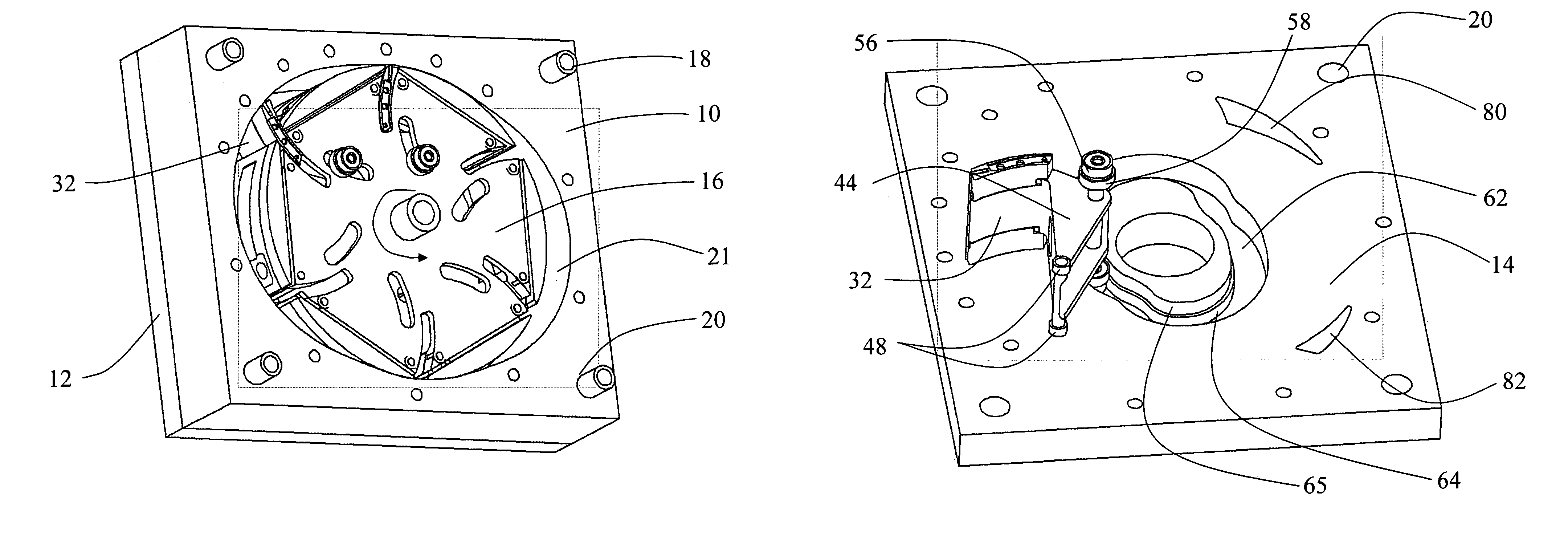
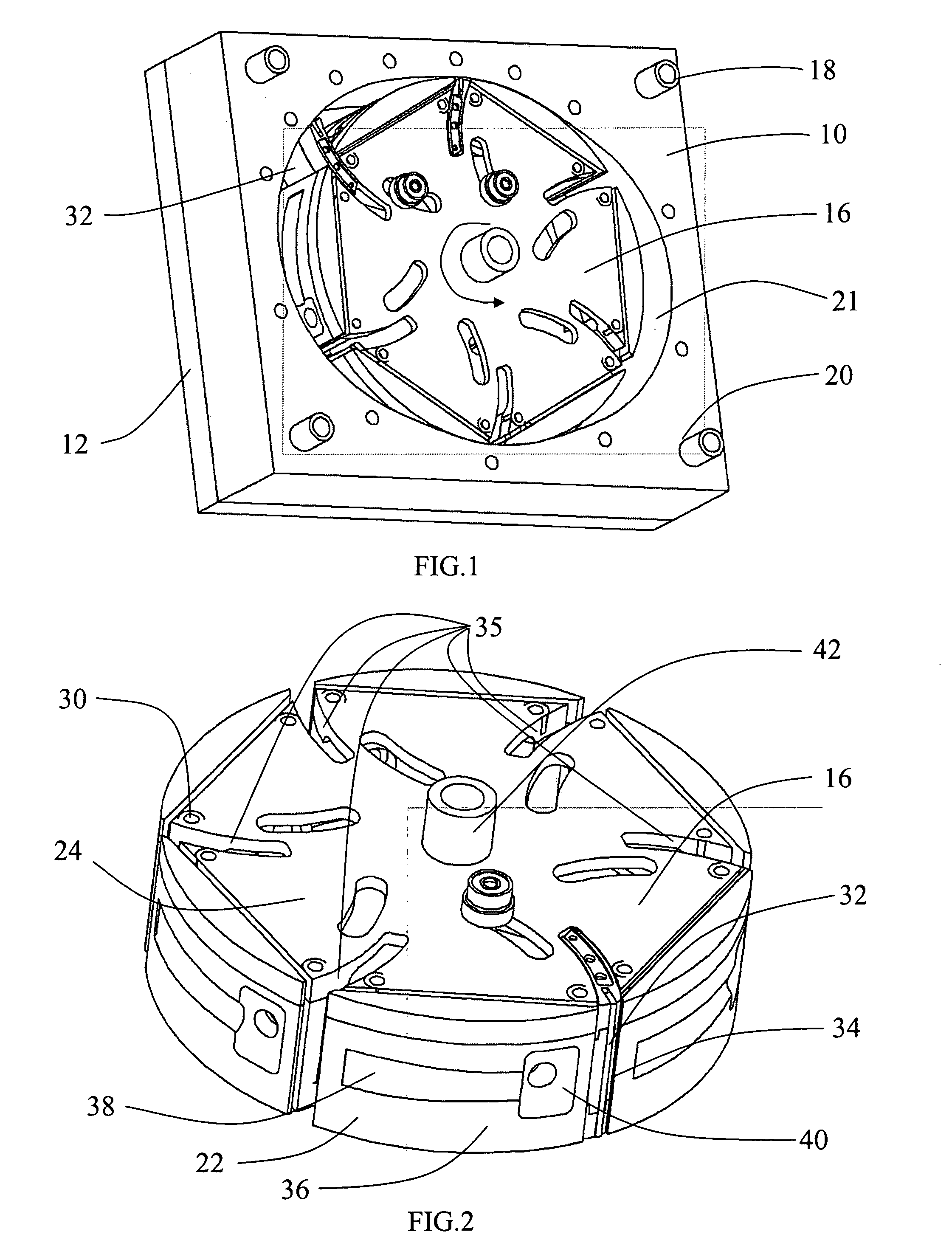
[0033]Referring to the drawings, in FIG. 1, an embodiment of an engine employing the present invention is shown. An outer structure including a case 10 with a bottom plate 12 (partially sectioned in the view) and top plate 14 (FIGS. 4a &5a) encloses a rotor 16. For the embodiment shown, the top and bottom plates align to the case with pins 18 received in holes 20.

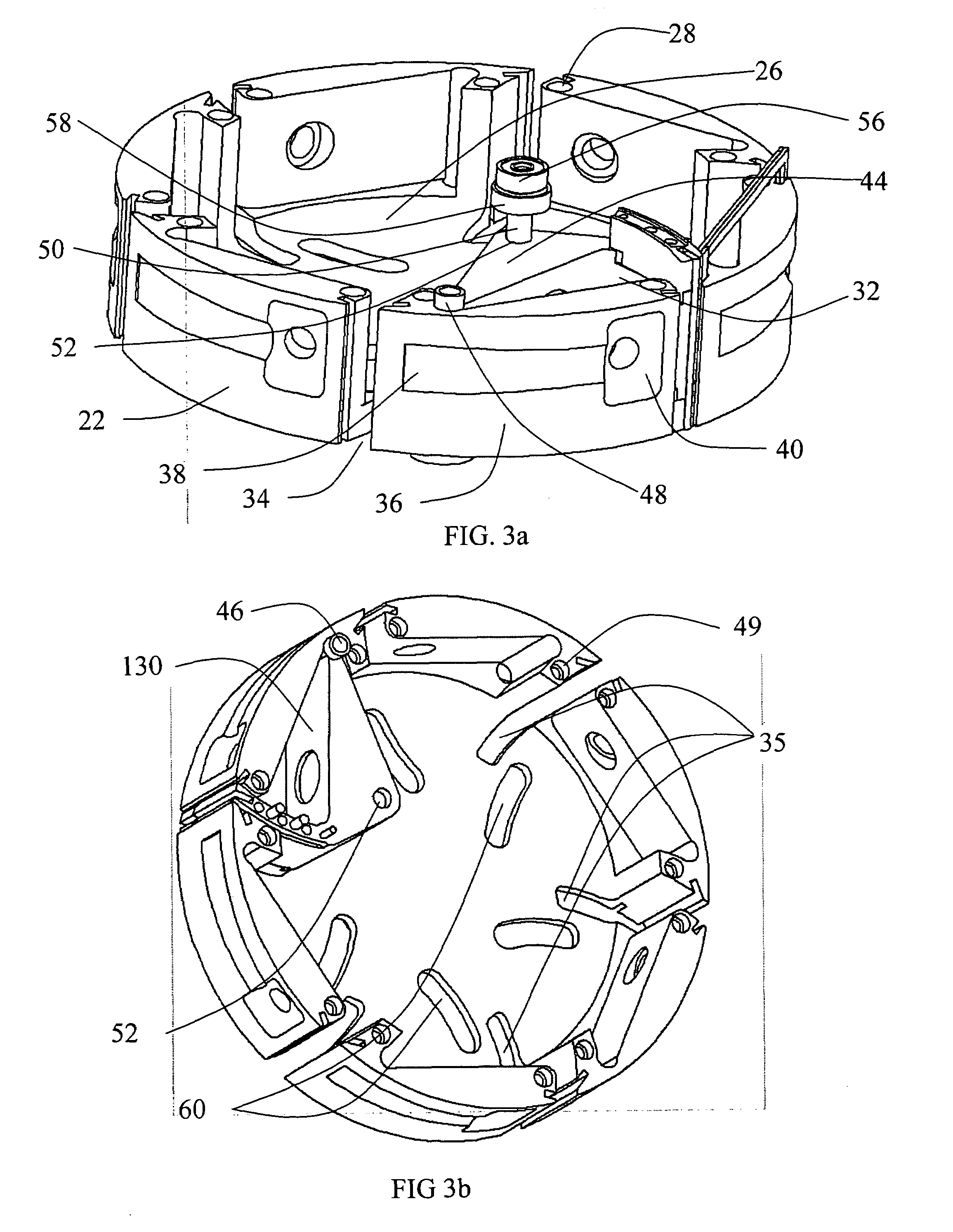
[0034]The rotor has a body 22 and a cover 24 as shown in FIG. 2 and in FIG. 3a with the cover removed to show the interior chamber 26 of the rotor. The cover is secured to the body of the rotor using bolts received in holes 28 through countersunk holes 30 in the cover. The rotor and cover are machined, sealed and bolted to form an airtight junction. Multiple lobes 32 are extendible and retractable into vertical slots 34 in the substantially cylindrical surface 36 of the rotor. Arcuate slots 35 in the rotor bottom and cover extend from the vertical slots to receive the lobes where they articulate from their pivot inside the ...


PUM


Abstract

A rotary engine with multiple pivotally mounted lobes desmodromically extendible and retractable from a rotor to trace asymmetric volumes for inlet and compression and expansion and exhaust based on the contour of the engine case which the lobes sealingly engage.

Description

REFERENCE TO RELATED APPLICATIONS[0001]This application claims priority of U.S. Provisional Application Ser. No. 60 / 617,466 filed on Oct. 7, 2004 and having the same title as the present application.BACKGROUND OF THE INVENTION[0002]1. Field of the Invention[0003]This invention relates generally to the field of rotary motion internal combustion engines and more particularly to an engine having a rotor with multiple lobes circumscribing asymmetric compression and expansion areas and providing multiple combustion cycles within a single rotation.[0004]2. Description of the Related Art[0005]Internal combustion engines with reciprocating pistons or circular motion rotors have been commonplace in the art for many years. Optimization of the mechanical systems associated with such engines to maximize the performance in thermodynamic efficiency, power output and emissions reduction while limiting mechanical complexity is continually ongoing. Rotary or Wankel engines typically reduce the numbe...

Claims


Application Information

Patent Timeline
Patent Type & Authority Patents(United States)
IPC IPC(8): F02B53/00F01C1/00F02B57/00F04C18/00F04C2/00
CPCF01C1/44F01C19/08F01C19/10F02B53/02F02B55/14Y02T10/17F02B2053/005F02B41/02Y02T10/12
Inventor PEITZKE, WILLIAM R.HOWES, LAWRENCEBROWN, MATTDEHLSEN, JAMES G. P.
Owner GYROTON CORP
Why Eureka
Try Eureka