Method and apparatuses for screening

a screening method and a technology of screening apparatus, applied in the direction of screening, chemistry apparatus and processes, solid separation, etc., can solve the problems of limiting productivity and use, maintenance and contamination problems, wear and replacement of screening screens, etc., to simplify the process of securing a replacement screen, cost effective, and quick installation

Active Publication Date: 2009-08-25
DERRICK CORP
View PDF7 Cites 93 Cited by
  • Summary
  • Abstract
  • Description
  • Claims
  • Application Information

AI Technical Summary

Benefits of technology

[0004]In an example embodiment of the present invention, a vibratory screening machine is provided that simplifies the process of securing a replaceable screen to the machine. The vibratory screening machine and replaceable screen prevent materials to be separated from flowing over the sides of the screen. The replaceable screen is designed to be cost effective and can be quickly installed on the vibratory screening machine.

Problems solved by technology

Over time, screens wear and require replacement.
Vibratory screening machines and their replaceable screens have several drawbacks that limit their productivity and use.
Replaceable screens have a substantially planar screen area and material often builds up at the screen edges causing maintenance and contamination problems.

Method used


Image

  • Method and apparatuses for screening
  • Method and apparatuses for screening
  • Method and apparatuses for screening

Examples


Embodiment Construction

[0038]Like reference characters denote like parts in the drawings.

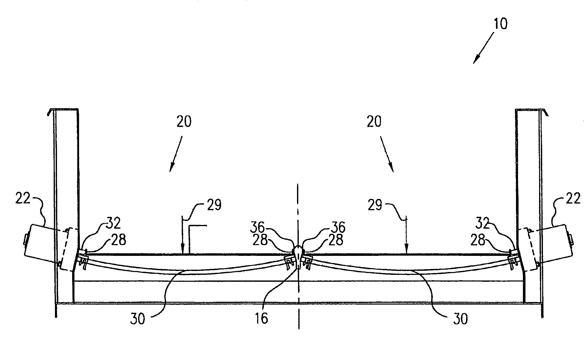
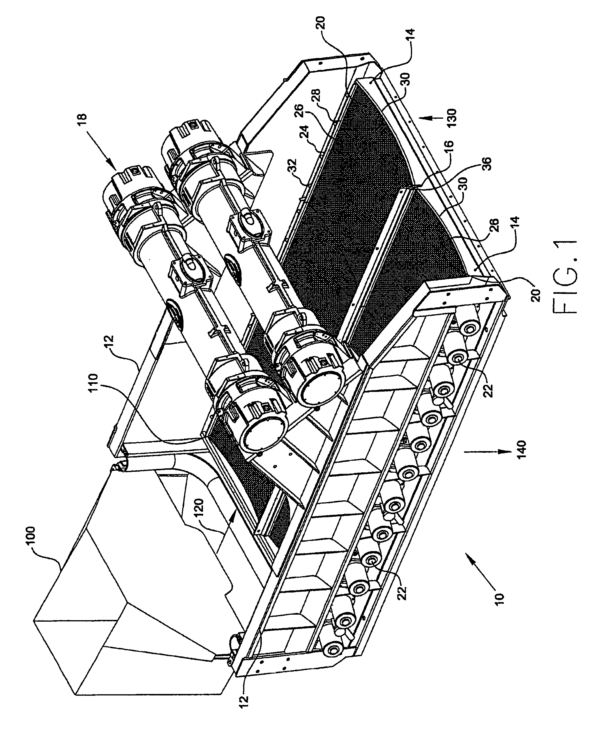
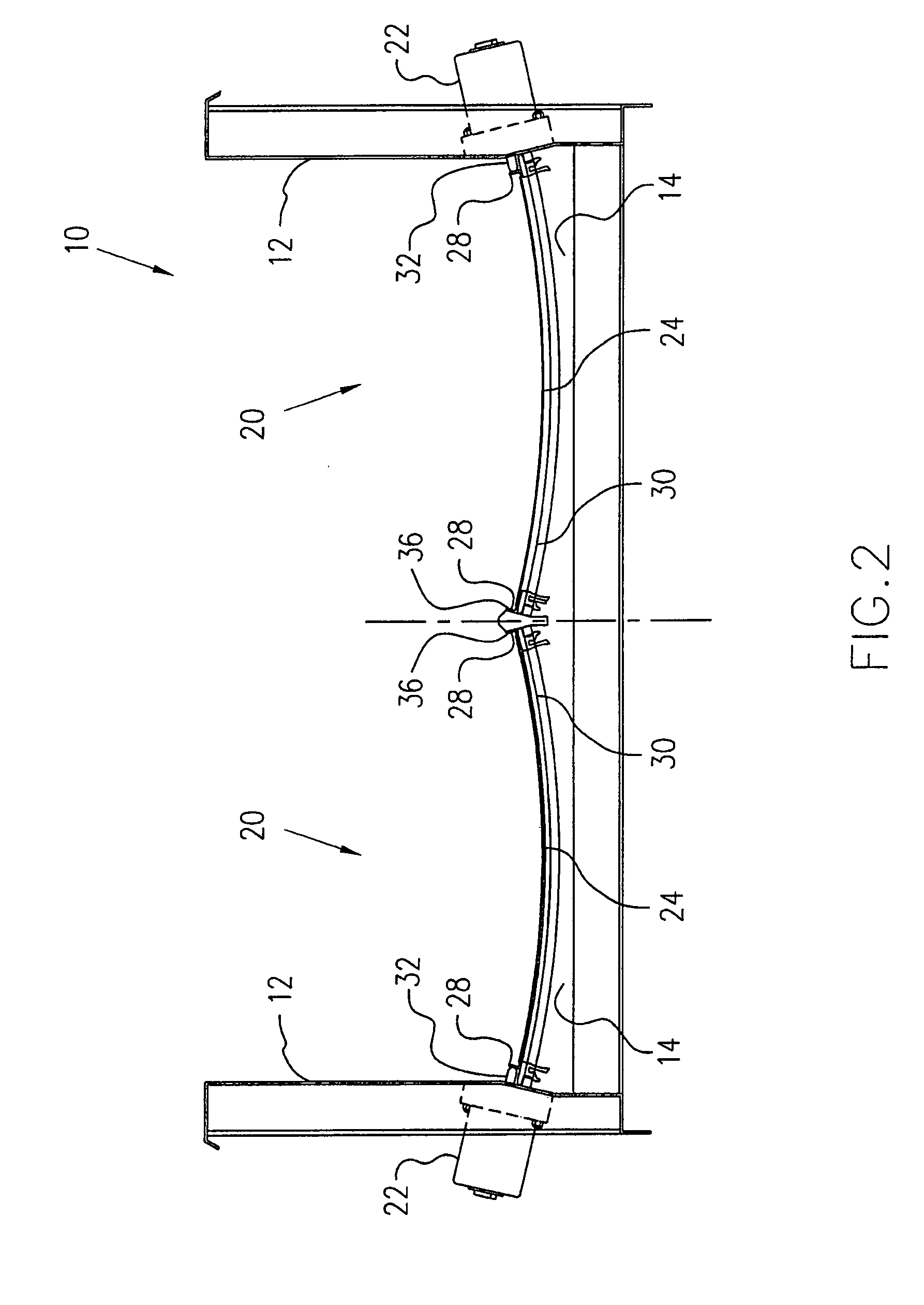
[0039]FIG. 1 shows vibratory screening machine 10 with installed replaceable screening assemblies 20. Material is fed into a feed hopper 100 and is then directed onto a top surface 110 of the screen assemblies 20. The material travels in flow direction 120 toward the vibratory screening machine 10 end 130. The material flowing in direction 120 is contained within the concave configuration provided by the screen assemblies 20. The material is prevented from exiting the sides of screen assemblies 20. Material that is undersized and / or fluid passes through screen assemblies 20 onto a separate discharge material flow path 140 for further processing. Materials that are oversized exit end 130. The material stream may be dry, a slurry, etc., and the screen assemblies 20 may be pitched downwardly from the hopper 100 toward an opposite end in the direction 120 to assist with the feeding of the material.

[0040]Vibratory screenin...


PUM


Abstract

A screening machine includes wall members, a screen assembly, and a compression assembly. The screen assembly includes a frame with a plurality of side members and a screen supported by the frame. The compression assembly is attached to at least one wall member and forms the screen assembly into a concave shape.

Description

FIELD OF THE INVENTION[0001]The present invention relates generally to material screening. More particularly, the present invention relates to a method and apparatuses for screening.BACKGROUND INFORMATION[0002]Material screening includes the use of vibratory screening machines. Vibratory screening machines provide the capability to excite an installed screen such that materials placed upon the screen may be separated to a desired level. Oversized materials are separated from undersized materials. Over time, screens wear and require replacement. As such, screens are designed to be replaceable.[0003]Vibratory screening machines and their replaceable screens have several drawbacks that limit their productivity and use. In vibratory screening machines, the material to be separated is placed on flat or corrugated replaceable screens. The replaceable screens are tensioned over a surface of the vibratory screening machine such that the replaceable screen tightly fits on the machine. A tens...

Claims


Application Information

Patent Timeline
Patent Type & Authority Patents(United States)
IPC IPC(8): B07B1/42B07B1/06
CPCB07B1/4645B07B1/485B07B1/48B07B2201/02B07B1/40B07B1/46
Inventor WOJCIECHOWSKI, KEITHNEWMAN, CHRISTIAN
Owner DERRICK CORP
Why Eureka
Try Eureka