Tool and a cutting insert for chip removing machining

a cutting tool and chip removal technology, which is applied in the direction of turning machine accessories, shaping cutters, manufacturing tools, etc., can solve the problem of limiting the length of cutting inserts from end to end, and achieve the effect of improving cutting, without reducing the ability of cutting tools to form and evacuate chips

Inactive Publication Date: 2009-08-25
SANDVIK INTELLECTUAL PROPERTY AB
View PDF11 Cites 5 Cited by
  • Summary
  • Abstract
  • Description
  • Claims
  • Application Information

AI Technical Summary

Benefits of technology

[0005]The present invention aims at obviating the above-mentioned shortcomings of previously known cutting tools and at providing an improved cutting tool. Therefore, an object of the invention is to provide a cutting tool, which can be equipped with a large number of cutting inserts per unit length without reducing the ability of the tool to form and evacuate chips. An additional object is to provide a cutting tool, the basic body of which can be made in a structurally easy manner at the same time as the cutting inserts can be fixed in a persistently stable manner on the basic body.

Problems solved by technology

Thus, the limiting factor of the number of cutting inserts is the length of the cutting inserts from end to end.

Method used


Image

  • Tool and a cutting insert for chip removing machining
  • Tool and a cutting insert for chip removing machining
  • Tool and a cutting insert for chip removing machining

Examples


Embodiment Construction

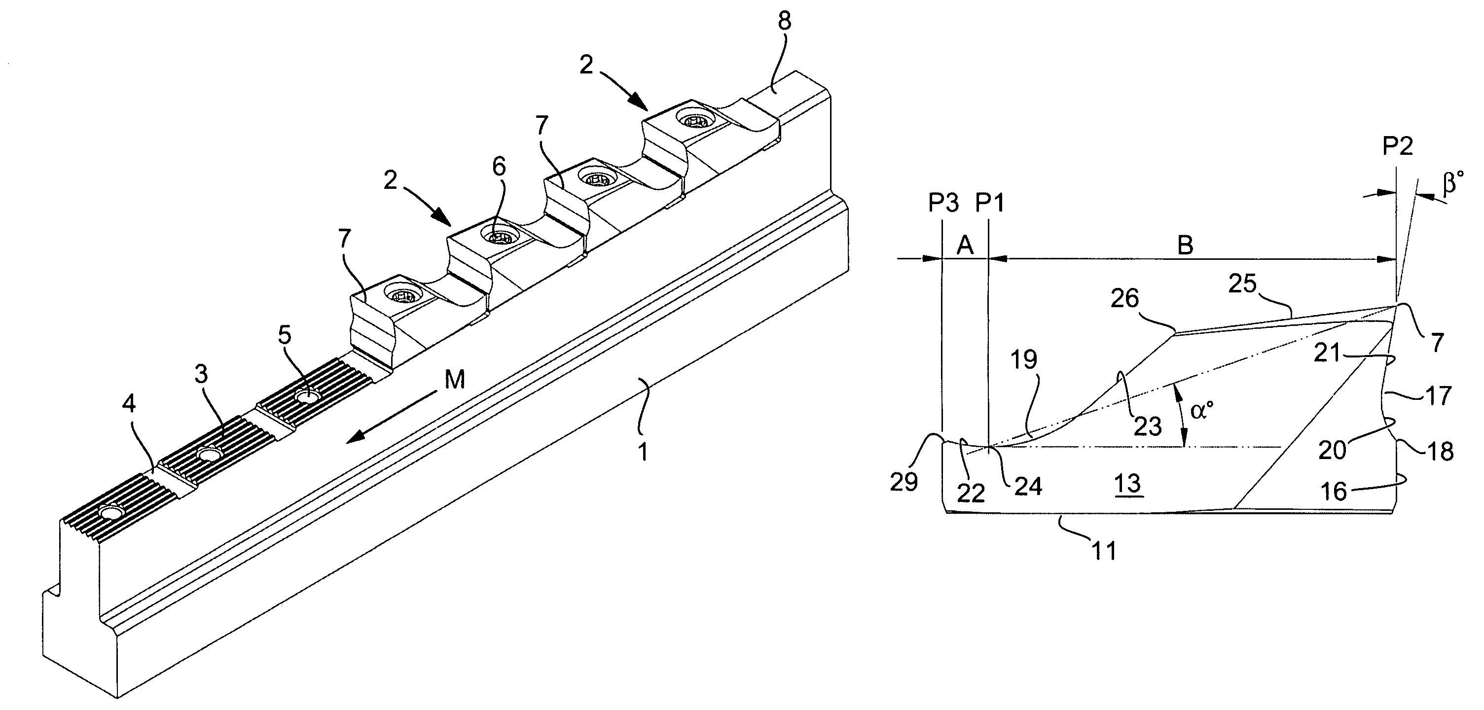
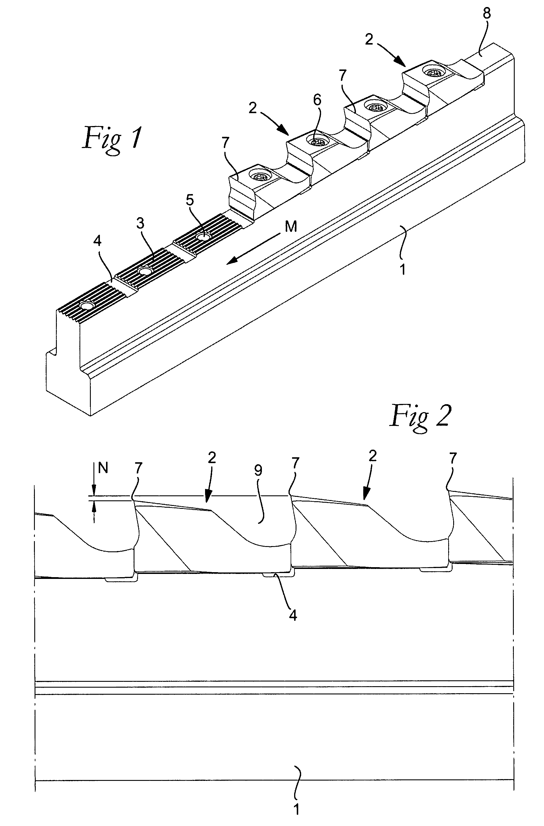
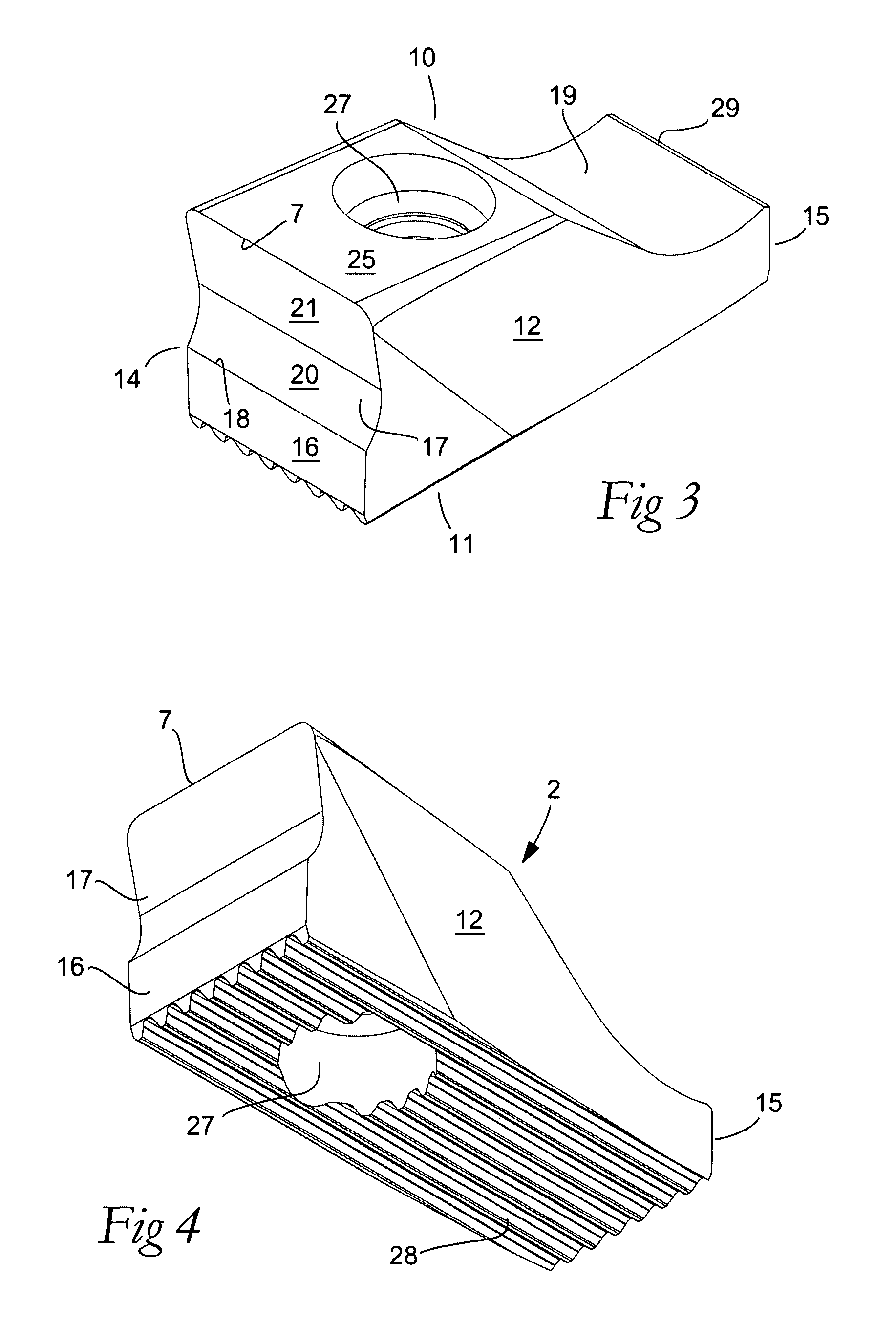
[0021]As an example of a cutting tool to which the invention may be applied, a reaming tool is shown in FIGS. 1 and 2. The tool includes a basic body 1, as well as a plurality of cutting inserts 2 arranged in series one after the other. In this case, the basic body has a long narrow, straight basic shape, which generally resembles a ruler or T-beam. In the example, respective inserts 2 are each mounted in an insert seat 3, which in this case is in the form of a serration connecting surface that only includes straight and parallel ridges and grooves, respectively, which extend axially in the length extension of the basic body. Adjacent insert seats 3 are mutually spaced-apart by clearance spaces in the form of transverse notches 4. In each insert seat, a threaded hole 5 mouths for a screw 6 for clamping the cutting insert in a desired seat along the basic body. Each individual cutting insert includes a cutting edge 7, which in the example is straight and extends essentially along the...


PUM

PropertyMeasurementUnit
angleaaaaaaaaaa
angleaaaaaaaaaa
anglesaaaaaaaaaa

Abstract

A cutting tool including a basic body and a plurality of cutting inserts arranged in series one after the other. Each insert includes a topside, an underside, two opposite side surfaces, front and rear ends, and a cutting edge adjacent to the front end. The rear end of a first cutting insert faces the front end of a second cutting insert disposed rearward of the first insert, and a chip space forward of the cutting edge of the second cutting insert is delimited by a chip-forming surface extending in the forward direction from the rear end of the first cutting insert, and a chip-forming surface extending downward from the cutting edge of the second cutting insert.

Description

[0001]This application claims priority under 35 U.S.C. § 119 to Sweden Patent Application No. 0601871-7, filed on Sep. 12, 2006, the disclosure of which is incorporated by reference herein in its entirety.FIELD OF THE INVENTION[0002]The present invention relates generally to a cutting tool for chip removing machining of the type that includes a basic body and a plurality of cutting inserts arranged in series one after the other, which individually include a topside, an underside, two opposite side surfaces, front and rear ends, and a cutting edge adjacent to the front end. The invention also relates to an individual cutting insert for such tools.BACKGROUND OF THE INVENTION[0003]Many types of tools for cutting or chip removing machining of, in particular, workpieces of metal, are made with a plurality of replaceable cutting inserts situated in series one after the other, of the type that are manufactured from a hard and wear-resistant material, such as cemented carbide, ceramics or t...

Claims


Application Information

Patent Timeline
Patent Type & Authority Patents(United States)
IPC IPC(8): B23P15/42
CPCB23B27/16B23C5/20B23D43/04B23D77/02B23B2210/02Y10T407/235Y10T407/16B23C2270/16B23D61/16
Inventor HESSMAN, INGEMARJOHANSSON, .ANG.KE
Owner SANDVIK INTELLECTUAL PROPERTY AB
Why Eureka
Try Eureka