
Articulating ionizable gas coagulator

a coagulator and ionizable technology, applied in the field of articulating ionizable gas coagulator, can solve the problems of repeat bleeding, difficult manipulation of instruments, and difficulty in eschar adherence,

Inactive Publication Date: 2009-08-25
COVIDIEN AG
View PDF148 Cites 13 Cited by
  • Summary
  • Abstract
  • Description
  • Claims
  • Application Information

AI Technical Summary

Benefits of technology

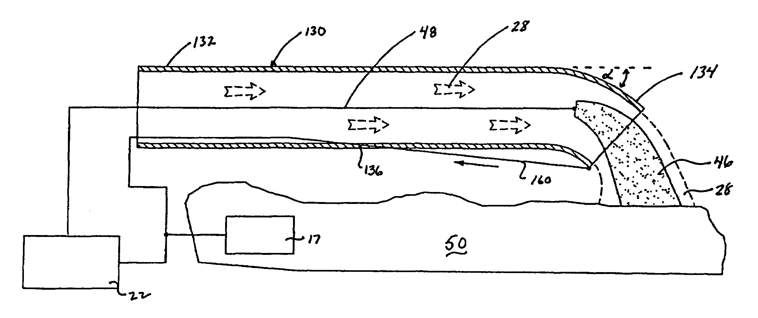
[0013]Another embodiment includes a corona electrode disposed proximate the distal end of the tube for inducing ignition of the gas prior to emission. A wire is used to articulate the distal end of the tube and direct the gas at the tissue. Preferably, the wire is connected to the corona electrode and electrically connects the corona electrode to a source of electrosurgical energy. A dielectric material is preferably disposed between the corona electrode and the active electrode to prevent arcing between electrodes.

Problems solved by technology

Smaller cannulas are usually preferred, and this presents a design challenge to instrument manufacturers who must find ways to make surgical instruments that fit through the cannulas and operate in a safe and effective manner.
However, due to space limitations surgeons can have difficulty manipulating the instrument to coagulate, desiccate, fulgurate and / or cut tissue.
Moreover, if the probe comes into close contact with the tissue, the probe may adhere to the eschar during probe removal possibly causing repeat bleeding.
Again, eschar adherence may also be a problem with these instruments.
In both types of instruments, the depth of the coagulation is difficult to control.
Using these instruments to treat certain more tubular sites, e.g., the esophagus and / or colon, is often difficult, impractical and time consuming.
Thus, manipulating these instruments to focus the energy transversely or off-axis at the bleeding tissue may be very difficult.

Method used


Image

  • Articulating ionizable gas coagulator
  • Articulating ionizable gas coagulator
  • Articulating ionizable gas coagulator

Examples


Embodiment Construction

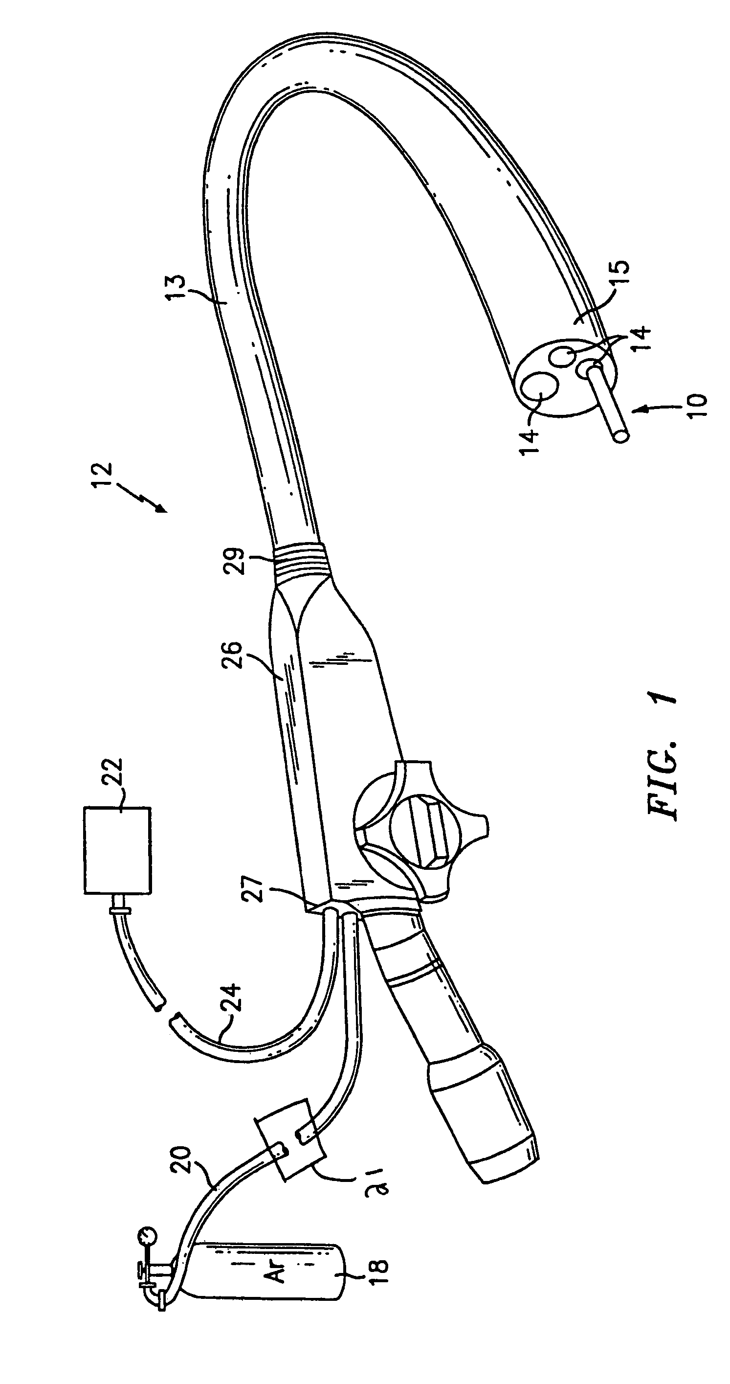
[0023]Referring now to FIG. 1, an articulating tissue coagulator generally identified by reference numeral 10 is shown extending through a working channel of an endoscope 12. Preferably, the coagulator 10 can be employed with a variety of different endoscopes such as those manufactured by Olympus, Pentax and Fujinon. As such, only the basic operating features of the endoscope 12 which work in combination with the present disclosure need to be described herein. For example, endoscope 12 includes a handpiece 26 having a proximal end 27 and a distal end 29. In the drawings and in the description which follows, the term “proximal”, as is traditional, will refer to the end of the apparatus which is closer to the user, while the term “distal” will refer to the end which is further from the user.

[0024]Preferably, the proximal end of the coagulator 10 is mechanically coupled to a supply 18 of pressurized ionizable gas, e.g., inert gas, by way of hose 20 and electrically coupled to an electr...


PUM


Abstract

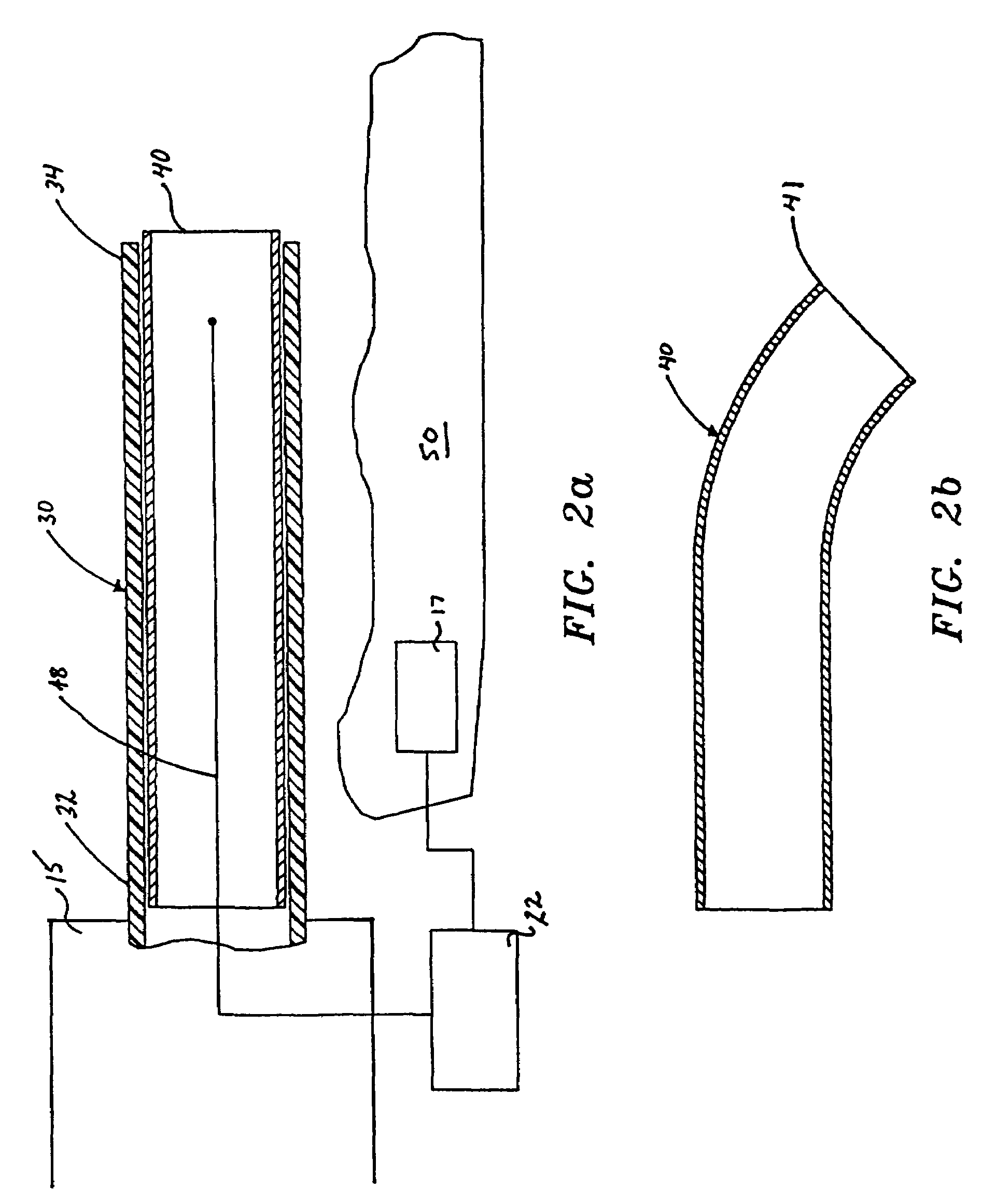
An electrosurgical apparatus for coagulating tissue includes an elongated flexible tube having a proximal end, a distal end and a source for supplying pressurized ionizable gas to the proximal end of the tube. The apparatus also includes a hollow sleeve made from a shape memory alloy having a generally curved austenite state and displaying stress-induced martensite behavior. The hollow sleeve is restrained in a deformed stress-induced martensite configuration within the tube and partial extension of a portion of the hollow sleeve from the tube transforms the portion of the sleeve from the deformed configuration to the generally curved austenite configuration such that the gas is directed transversely at the tissue. An electrode ionizes the gas in the region between the sleeve and the tissue. Other embodiments of the present disclosure also include a wire connected to the distal end of the tube which movable from a first postion wherein the tube is disposed in a generally rectilinear, parallel fashion relative to the tissue to a second retracted position wherein the distal end of the tube flexes at an angle to direct the gas towards the tissue. Still other embodiments of the present disclosure include a corona electrode for inducing ignition of the gas.

Description

CROSS REFERENCE TO RELATED APPLICATION[0001]The present application is a continuation of U.S. patent application Ser. No. 10 / 282,288 filed on Oct.28, 2002 now U.S. Pat. No. 6,911,029 by Robert C. Platt, which is a continuation of U.S. patent application Ser. No. 09 / 665,380 filed on Sep. 21, 2000 now U.S. Pat. No. 6,475,217 by Robert C. Platt, which claims priority to U.S. Provisional Application Ser. No. 60 / 157,743 filed on Oct. 5, 1999, the entire contents of all of which are hereby incorporated by reference herein.[0002]The present disclosure relates to gas-enhanced electrosurgical instruments for coagulating tissue. More particularly, the present disclosure relates to an articulating, gas-enhanced electrosurgical apparatus for coagulating tissue.BACKGROUND OF RELATED ART[0003]Over the last several decades, more and more surgeons are abandoning traditional open methods of gaining access to vital organs and body cavities in favor of endoscopes and endoscopic instruments which acces...

Claims


Application Information

Patent Timeline
Patent Type & Authority Patents(United States)
IPC IPC(8): A61B18/18A61B17/00A61B18/00A61B18/14
CPCA61B18/042A61B2017/00292
Inventor PLATT, ROBERT C.
Owner COVIDIEN AG
Learn More