Light-emitting apparatus package, light-emitting apparatus, backlight apparatus, and display apparatus

a technology of light-emitting apparatus and backlight, which is applied in the direction of instruments, semiconductor lasers, optical elements, etc., can solve the problems of less than expected luminosity, adverse effects on reliability, and thin thickness of the support section so as to improve the radiation property of the light-emitting device, improve the luminosity, and improve the stability

Active Publication Date: 2009-08-25
XIAMEN SANAN OPTOELECTRONICS CO LTD
View PDF19 Cites 56 Cited by
  • Summary
  • Abstract
  • Description
  • Claims
  • Application Information

AI Technical Summary

Benefits of technology

[0014]An object of the present invention is to provide (i) a light-emitting apparatus package which causes luminosity, stability, radiation property of the light-emitting device to be improved, (ii) a light-emitting ap...

Problems solved by technology

On this account, luminosity increases less than expected and the reliability is affected adversely.
Furthermore, because the light-emitting apparatus is required to be downsi...

Method used


Image

  • Light-emitting apparatus package, light-emitting apparatus, backlight apparatus, and display apparatus
  • Light-emitting apparatus package, light-emitting apparatus, backlight apparatus, and display apparatus
  • Light-emitting apparatus package, light-emitting apparatus, backlight apparatus, and display apparatus

Examples


first embodiment

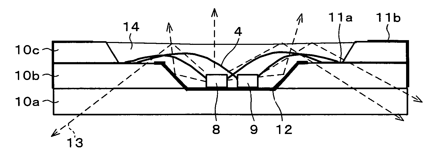
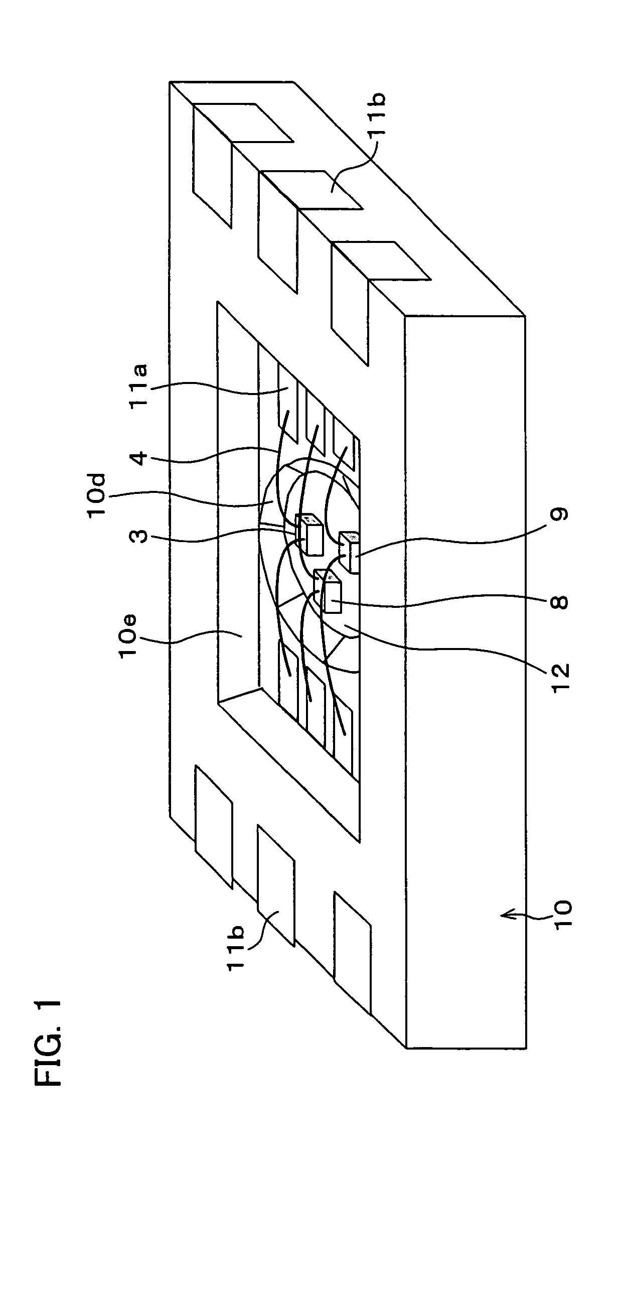
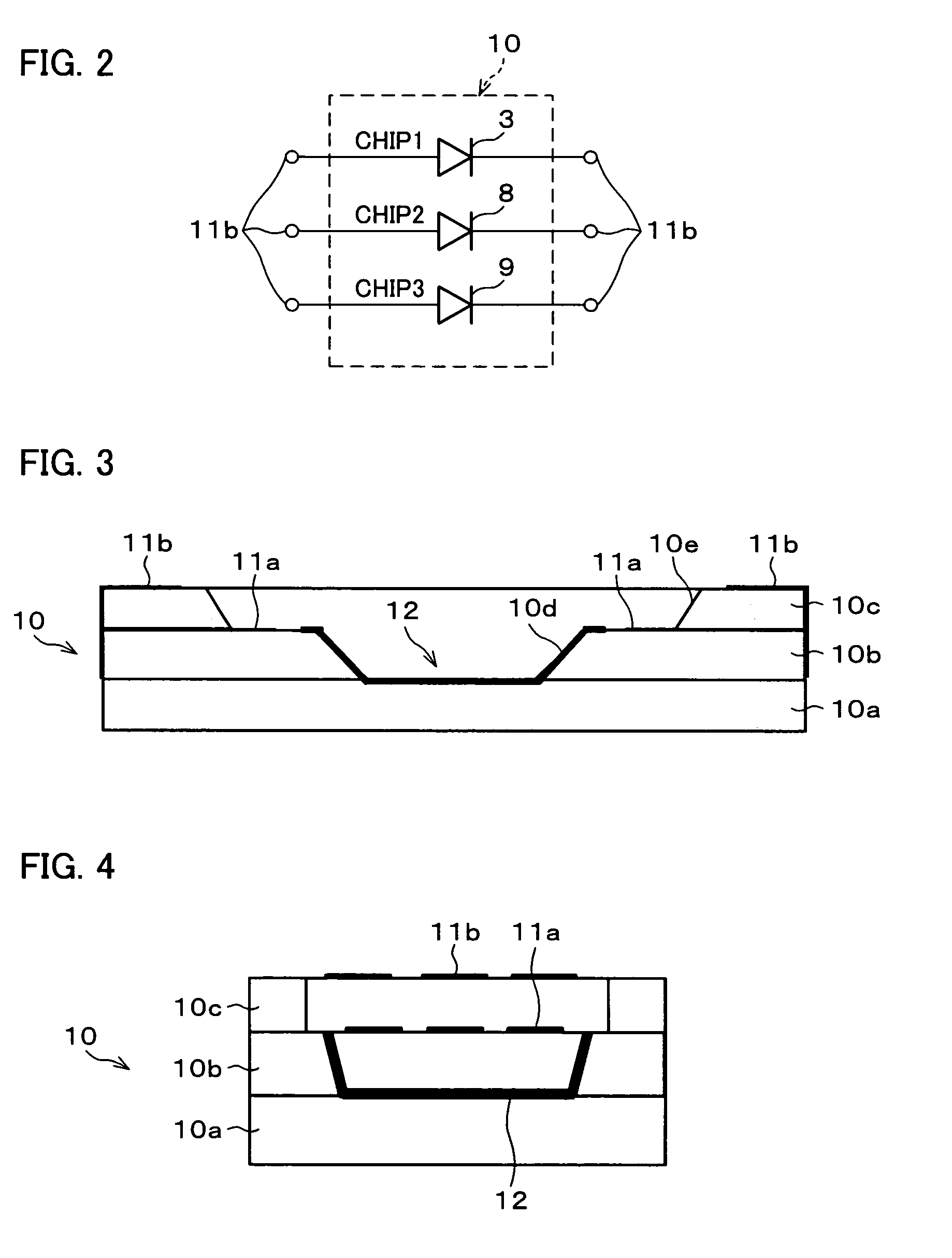
[0098]As shown in FIG. 1 and FIG. 2, a light-emitting apparatus in accordance with the present invention includes a plurality of light-emitting devices, for example three light-emitting devices 3, 8, and 9 in a light-emitting apparatus package of ceramic substrate type in accordance with the present invention. The light-emitting devices 3, 8, and 9, are exemplified by rectangular-shaped LED and semiconductor laser.

[0099]The light-emitting apparatus package includes (i) a ceramic substrate 10 having electric insulation and good thermal conduction, (ii) a first concave section 10e formed by hollowing out the ceramic substrate 10 in its thickness direction such that a light exit aperture is provided, (iii) a second concave section 10d formed by further hollowing out the first concave section 10e in the thickness direction such that the light-emitting devices 3, 8, and 9 are provided therein, and (iv) wiring patterns 11a, provided in the first concave section 10e, for supplying electric...

second embodiment

[0121]As shown in FIG. 5, the respective light 13 irradiated from the light-emitting devices 3, 8, and 9 may be reflected at the top surface of the transparent resin section 14 which seals the light-emitting devices 3, 8, 9 and the Au wires 4. The light thus reflected becomes the stray light directing to unintended directions.

[0122]In order to prevent the stray light, in the second embodiment of the present invention, as shown in FIG. 7 and FIG. 8, another metalized layer 15 having light reflectivity and heat-conduction is provided in addition to the metalized layer 12, under the layer where the wiring patterns 11a, to which the Au wires 4 are respectively connected, are provided. In other words, the metalized layer 15 is provided so as to extend from the end of the metalized layer 12 to such an area as to face the wiring patterns 11a in the thickness direction.

[0123]The metalized layer 15 may be arranged so as to reach a peripheral edge part of the substrate 10b other than a periph...

third embodiment

[0129]In Third Embodiment, a light-emitting apparatus package in accordance with the present invention, as shown in FIG. 15 and FIG. 16, in addition to the arrangement of the First Embodiment, a reflective section 18, which reflects the incident light, is formed by printing on an area other than the area where the wiring patterns 11a are provided on the internal surface of the first concave section 10e on which Au wires are provided.

[0130]In the Third Embodiment, because the reflective section 18 reflects the incident light to the area other than the area where the wiring patterns 11a are provided, it is possible to suppress the light directing to an area other than the light exit aperture. This ensures to improve the utilization efficiency of the light. The Third Embodiment may be combined with the First Embodiment, the Second Embodiment or other embodiments described below. This ensures to improve the utilization efficiency of the light.


PUM


Abstract

A light-emitting apparatus package of the present invention includes (i) an electrically insulated ceramic substrate, (ii) a first concave section formed in the direction of thickness of the ceramic substrate so as to form a light exit aperture in a surface of the ceramic substrate, (iii) a second concave section formed within the first concave section in the further direction of thickness of the ceramic substrate so that one or more light-emitting devices are provided therein, (iv) a wiring pattern for supplying electricity, which is provided in the first concave section, and (v) a metalized layer having light-reflectivity, which is (a) provided between the light-emitting device and the surface of the second concave section of the substrate, and (b) electrically insulated from the wiring pattern. On the account of this, the light-emitting apparatus package in which heat is excellently discharged and light is efficiently utilized and a light-emitting apparatus in which the light-emitting apparatus package is used can be obtained.

Description

[0001]This Nonprovisional application claims priority under 35 U.S.C. §119(a) on Patent Application No. 2003 / 98554 filed in Japan on Apr. 1, 2003, and Patent Application No. 2003 / 104669 filed in Japan on Apr. 8, 2003, the entire contents of which are hereby incorporated by reference.FIELD OF THE INVENTION[0002]The present invention relates to (i) a light-emitting apparatus package for a light source, driven by a large current intensity, such as a backlight source, such as a light-emitting diode, used for a liquid crystal display (LCD) and an illumination light source, (ii) a light-emitting apparatus in which the light-emitting apparatus package is used, (iii) a backlight apparatus in which the light-emitting apparatus is used, and (iv) a display apparatus in which the backlight apparatus is used.BACKGROUND OF THE INVENTION[0003]In a conventional light-emitting apparatus of surface-mounted type, light-emitting device as shown in FIG. 62 and FIG. 63, a light-emitting device 3 such as ...

Claims


Application Information

Patent Timeline
IPC IPC(8): H01L33/00G02F1/1335G02F1/13357H01L25/075H01L33/46H01L33/48H01L33/62H01L33/64H01S3/04H01S5/00H05B44/00
CPCH01L25/0753H01L33/486H01L24/97H05B33/06H01L33/46H01L33/62H01L33/641H01L2224/48227H01L2924/12041H01L2224/45144H01L2224/48091H01L2924/00014H01L2924/00H01L2924/351H01L2924/15787H01L2924/181H01L2924/12042H01L2924/14H01L24/45H01L24/48H05B45/56H01L2224/45015H01L2924/207H01L2224/85399H01L2224/05599G02B6/0073H01L25/167H01L33/56H01L33/60H01L33/64H01L2224/48106H01L2924/19041H01L2924/19105
Inventor INOGUCHI, TSUKASA
Owner XIAMEN SANAN OPTOELECTRONICS CO LTD
Why Eureka
Try Eureka