Projection system with safety detection

a projection system and safety detection technology, applied in the direction of picture reproducers, picture reproducers using projection devices, instruments, etc., can solve the problems of stringent safety regulations restricting their use, excessive output power of laser sources, and easy blind spots

Active Publication Date: 2017-09-14
BARCO NV
View PDF2 Cites 25 Cited by
  • Summary
  • Abstract
  • Description
  • Claims
  • Application Information

AI Technical Summary

Benefits of technology

[0042]A drone or unmanned aerial vehicle according to embodiments of the present invention can include a projector and a stabilizer, or a projector-stabilizing mount. Such stabilizers or stabilizing mounts have been developed for stabilization of cameras and can be applied to an on-board projector according to embodiments of the invention. Such a device holds a projector in a manner ...

Problems solved by technology

Their main drawback however is the stringent safety regulations restricting their use.
However, for a projection system, the output power of the laser source will exceed the emission levels of these two classes.
Both prior art solutions described above have the intrinsic property of being susceptible to blind spots.
Close by the lens or light source of the projecting system there will always be spots were an object will not be i...

Method used


Image

  • Projection system with safety detection
  • Projection system with safety detection
  • Projection system with safety detection

Examples


first embodiment

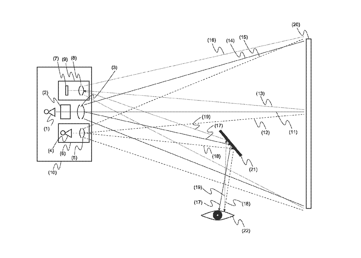
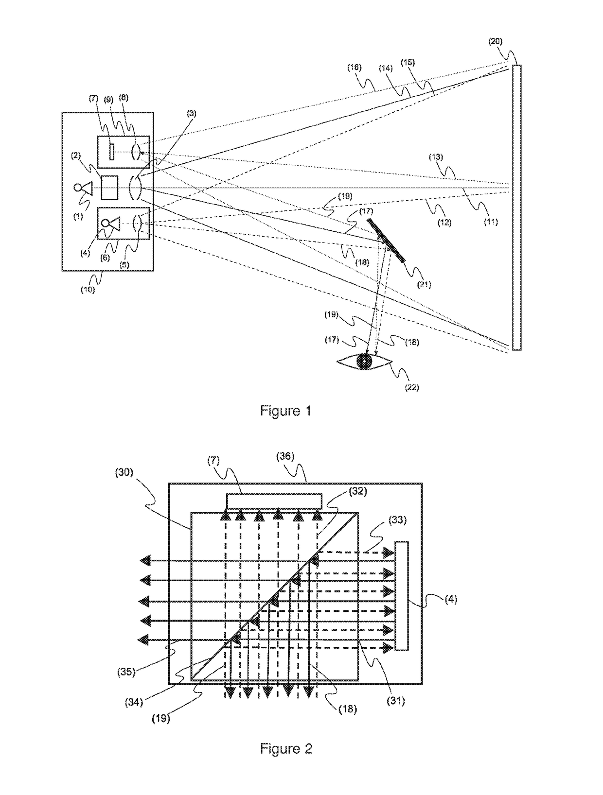
[0058]As an optional first step towards specific embodiments of the invention, the optical axis of the detection sensor (7) or camera and the optical axis of the light from the detection light source (12) are made the same or even identical in a detection sub-system. In said detection subsystem, this is achieved by using an optical component such as for beam splitting of the detection light (18) and reflected detection light (19). FIG. 2 shows such a detection subsystem (36) with the detection light source (4), detection sensor (7) or camera and a beam splitter (30). The irradiated detection light (31) that is irradiated by the detection light source (4) is reflected internally in the beam splitter (30) on a partially reflective surface (34). The reflected detection light (19) that was reflected back from an object or the projecting surface (20) will enter the beam splitter and will partially (32) hit on the detection sensor or camera and partially be reflected (33) to the detection...

second embodiment

[0060]In the sub-system that makes the optical axis of the detection sensor (7) and detection light source (4) the same or even identical, use is made of an optical component such as photosensitive elements and detection light emitting elements that are integrated on a single semiconductor substrate. Such so called bidirectional sensors have been demonstrated by the Fraunhofer institute using green OLED emitters (http : / / www.oled-info.com / fraunhofer-shows-new-bi-directional-oled-microdisplay-can-measure-distances).

third embodiment

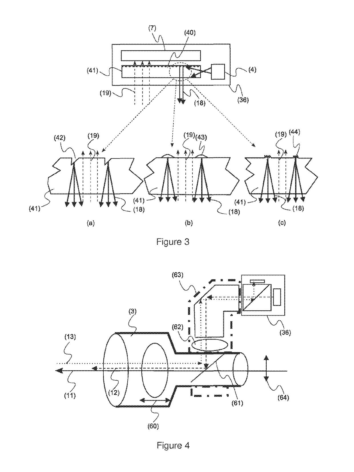
[0061]In said detection sub-system (see FIG. 3), the combination of the optical axes can be achieved by the use of an optical component such as a light guide (41) placed in front of the detection sensor (7) or camera. The light guide is based on similar technology as edge lit backlights. By adding a patterned dot structure (40) on the light guide it is determined where the light is coupled out from the light guide. Ideally this pattern is placed in the inactive areas between the sensor pixels of the detection sensor (7). Due to the small size of the detection sensor pixels it might be challenging to achieve this level of precision and alignment. Alternatively a random pattern of dots could be used. The dot size is preferably smaller than the size of a sensor pixel. It is important that the dot pattern directs the light as much as possible to the front so that the detection light (18) does not scatter back towards the detection sensor (7). The effect of this backscattering can be red...


PUM


Abstract

A projection system including a safety detection system for a protected space, said projection system including a projection light source, a projection imaging system, a projection lens system, a detection source comprising at least of a detection light source and a detection camera comprising at least of a detection sensor, characterized by the fact that the optical axis of the projection source is identical to the optical axis of the detection source and the detection camera at least in the protected space.

Description

RELATED APPLICATIONS[0001]This application is a continuation in part of application Ser. No. 14 / 426,770 filed on Mar. 9, 2015, that is national stage of PCT / M2013 / 058305 filed on Sep. 5, 2013, that claims the benefit of GB 1216129.5 filed on Sep. 11, 2012. All of which are herein incorporated by reference in their entirety.[0002]The current invention relates to a projection system with projection screen detection and optional safety protection as well as methods for producing and operating such systems. In particular the present invention relates to gyroscopically stabilized projector e.g. for the stabilization of projected images, e.g. as projected from a drone or unmanned aerial vehicle.BACKGROUND OF THE INVENTION[0003]Projecting systems used to project still images, motion pictures or visual effects on a projection surface are widely used nowadays in for example cinemas, home cinemas, presentation rooms, exhibition areas, light shows, etc In most implementations (see FIG. 1), a p...

Claims


Application Information

Patent Timeline
IPC IPC(8): G03B21/20H04N9/31
CPCG03B21/2086H04N9/3161G03B21/204G03B17/54G03B21/2033H04N9/3194G03B21/147
Inventor MAES, DIRK
Owner BARCO NV
Why Eureka
Try Eureka