
Method and micro power generator for generating electrical power from low frequency vibrational energy

a low frequency vibrational energy and micro-power generator technology, applied in the direction of generators/motors, machines/engines, mechanical equipment, etc., can solve the problems of limited life time and unsatisfactory effects

Active Publication Date: 2009-08-25
RGT UNIV OF MICHIGAN
View PDF7 Cites 40 Cited by
  • Summary
  • Abstract
  • Description
  • Claims
  • Application Information

AI Technical Summary

Benefits of technology

The present invention provides a method and micro power generator for generating electrical power from low frequency vibrational energy. The method involves receiving low frequency vibrational energy and converting it to vibrational energy with a higher frequency. This higher frequency energy can then be converted to electrical power using electromagnetic, piezoelectric, or electrostatic methods. The low frequency vibrational energy can be received through a mechanical resonator device that resonates at a frequency between 1 to 10 Hz. The high frequency vibrational energy can be converted using a micromechanical second resonator device that resonates at a frequency between 1 to 10 kHz. The generator can include a circuit that combines the two resonator devices so that they resonate at different frequencies. The invention provides a way to generate electrical power from low frequency vibrational energy, which can be useful in various applications such as energy harvesting or powering low-power electronic devices.

Problems solved by technology

Although electrochemical batteries and micro-fuel cells can provide more power, they are not desirable for some applications due to chemicals and reactions involved during the generation process.
Also, they have a limited life time.
Most reported devices are only capable of operating at frequencies of several kHz; at lower frequencies they are ineffective.

Method used


Image

  • Method and micro power generator for generating electrical power from low frequency vibrational energy
  • Method and micro power generator for generating electrical power from low frequency vibrational energy
  • Method and micro power generator for generating electrical power from low frequency vibrational energy

Examples


Embodiment Construction

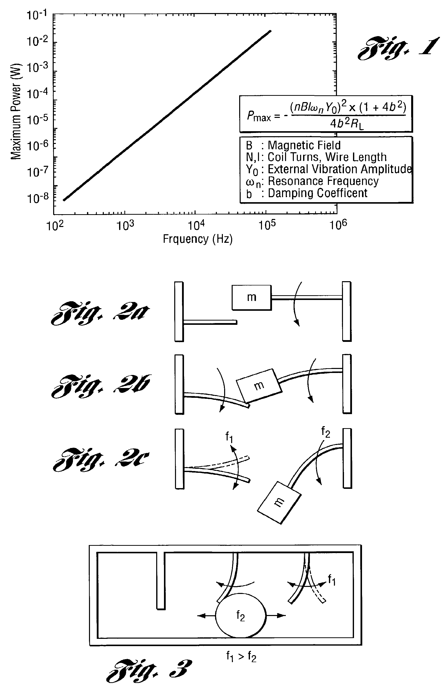
[0052]One of the main ideas for the power generation method and generator presented herein is mechanical frequency up-conversion. This mechanical up-conversion can be done in several different ways. One simple method to implement this is to use two cantilevers across each other as shown in FIG. 2(a). The cantilever on the right has a mass on the tip, and its resonance frequency is adjusted for the target ambient vibration frequency (f2=1-100 Hz). As this cantilever resonates with environmental vibration, at some point of its trajectory it touches or engages the cantilever on the left and forces it to move from its stationery position (FIG. 2b). When the right cantilever disengages the left cantilever, the right cantilever continues on with its movement, but at this time the left cantilever starts to resonate at its resonance frequency (f1), which is designed to be much higher than f2 (FIG. 2c). This happens again and again at each cycle of the right cantilever. For each cycle of the...


PUM


Abstract

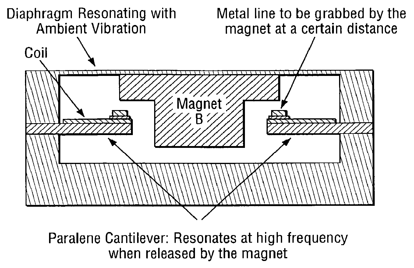
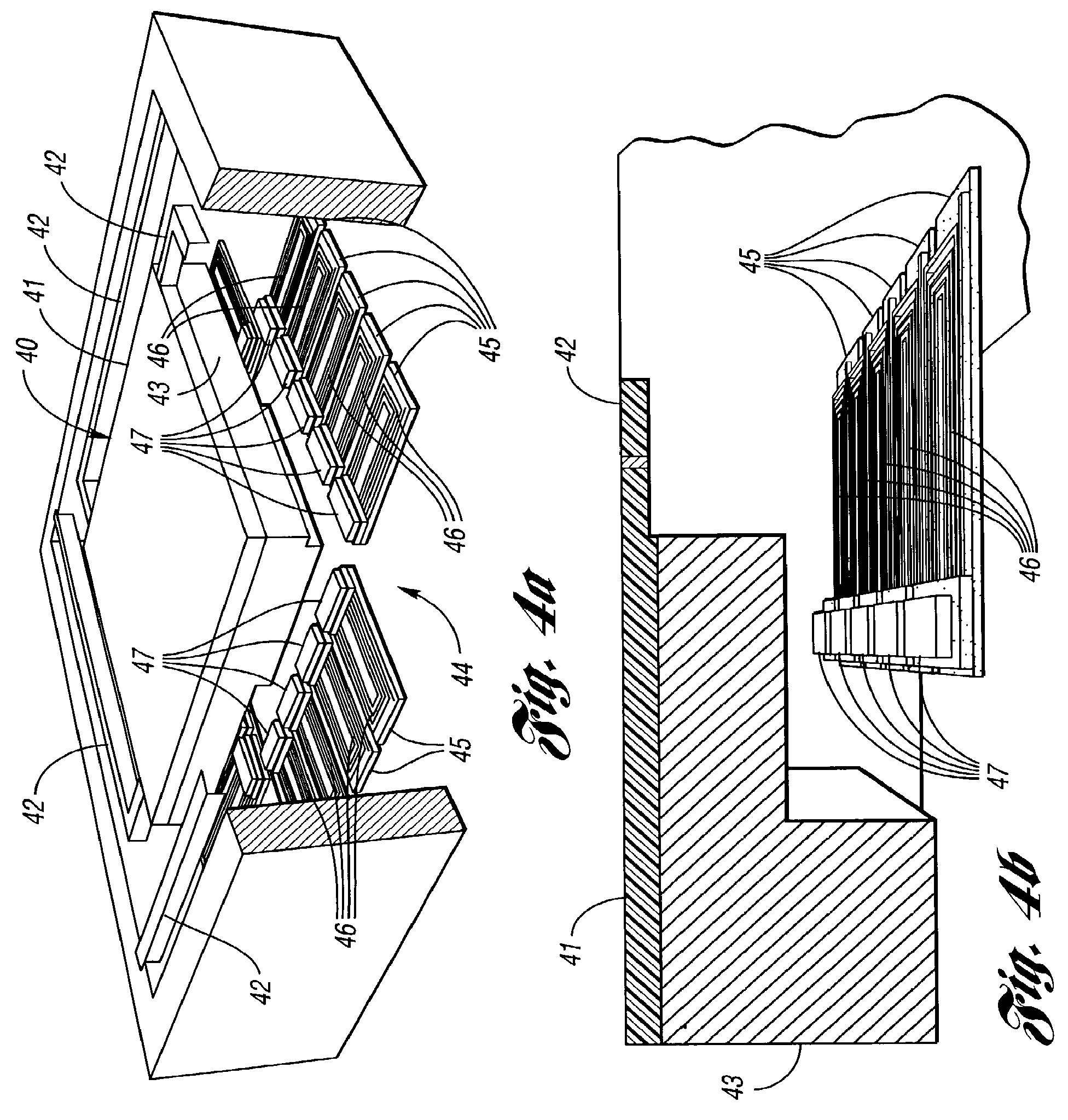
A method and a micro power generator for generating electrical power from low frequency, vibrational energy includes a frequency up-conversion process. The generator is preferably an electromagnetic, vibration-to-electrical power generator which can efficiently scavenge energy from low frequency external vibrations. The generator up-converts low frequency environmental vibrations to a much higher frequency through a mechanical frequency up-converter, and hence provides efficient energy conversion even at low frequencies. This mechanical frequency up-conversion process can be realized in a number of ways. A magnetic method is described as an example. After frequency up-conversion, voltage is induced on coils mounted on resonators by electromagnetic induction. Due to the movement of the coils on their respective resonating cantilevers with respect to the magnet, voltage is generated on the coils and energy conversion is realized.

Description

CROSS-REFERENCE TO RELATED APPLICATION[0001]This application claims the benefit of U.S. provisional application Ser. No. 60 / 537,821, filed Jan. 21, 2004 and entitled “Electromagnetic Micro Power Generator for Low Frequency Environmental Vibrations by Using Mechanical Frequency Up-Conversion.”STATEMENT REGARDING FEDERALLY SPONSORED RESEARCH OR DEVELOPMENT[0002]This invention was made with Government support from the National Science Foundation under NSF Grant No. EEC 9986866. The Government has certain rights in the invention.BACKGROUND OF THE INVENTION[0003]1. Field of the Invention[0004]This invention relates to methods and micro power generators for generating electrical power from low frequency vibrational energy.[0005]2. Background Art[0006]The following references are referenced herein:[0007][1] B. Koenaman et al., “Feasibility of Micro Power Supplies for MEMS,” JMEMS, Vol. 6, No. 4, pp. 355-362, December 1997.[0008][2] M. Mizuno et al, “Investigation of a Resonance Microgenera...

Claims


Application Information

Patent Timeline
Patent Type & Authority Patents(United States)
IPC IPC(8): H01L41/113H02K35/02H10N30/00H02N1/06H10N30/30
CPCF03G7/00F03G7/08H02N2/186H02K35/02H02N1/06H01L41/1136H10N30/306
Inventor KULAH, HALUKNAJAFI, KHALIL
Owner RGT UNIV OF MICHIGAN
Learn More