
System and method for efficient wide dynamic range coil drive

a wide dynamic range, coil drive technology, applied in the direction of motor/generator/converter stopper, process and machine control, electric/dynamo-electric converter starter, etc., can solve the problems of linear drive being generally inefficient, noise/ripple free cancelling force, etc., to achieve efficient high output force, low noise, and high resolution

Active Publication Date: 2009-08-25
HONEYWELL INT INC
View PDF10 Cites 1 Cited by
  • Summary
  • Abstract
  • Description
  • Claims
  • Application Information

AI Technical Summary

Benefits of technology

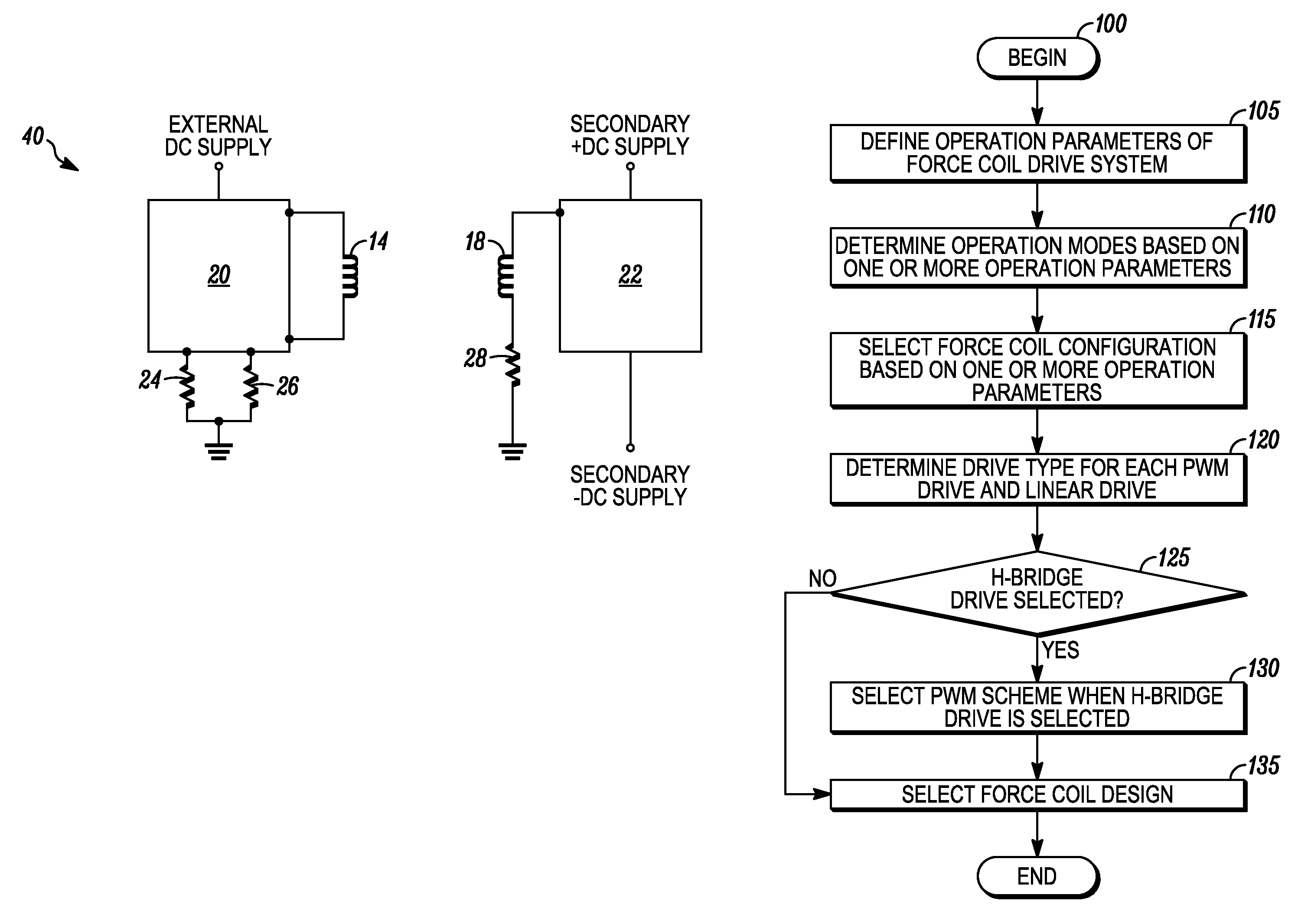
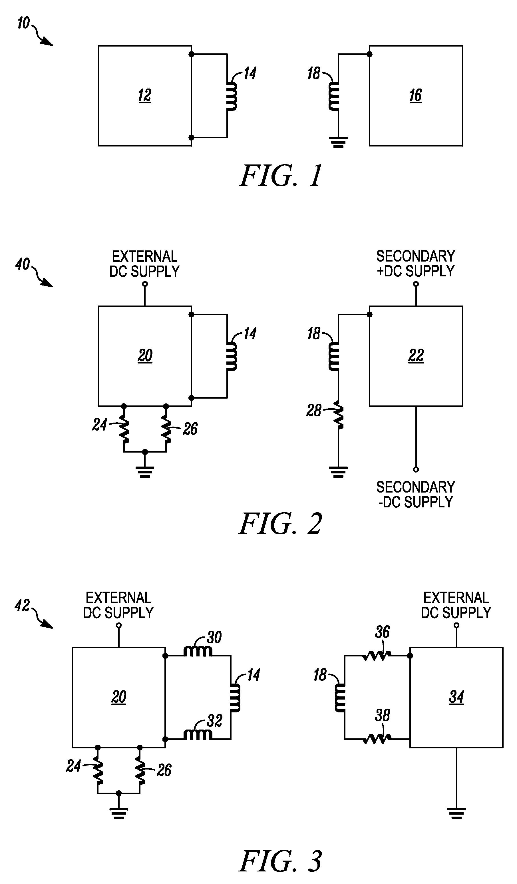
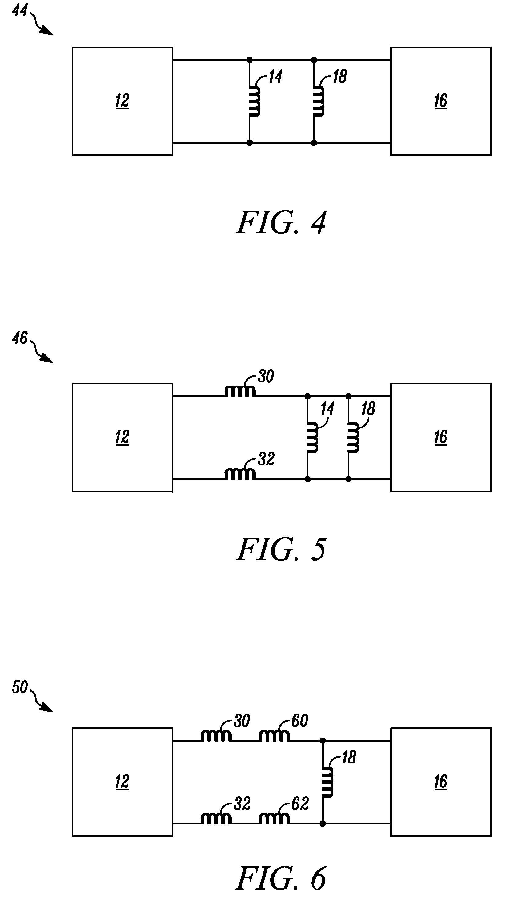
[0013]Systems and methods are provided for efficiently driving one or more force coils to produce output forces over a wide range with higher resolution than obtainable with conventional force coil drive systems. In an exemplary embodiment, a system for driving force coils is provided comprising a pulse width modulation (PWM) drive having an output for coupling to a first coil of the force coils, and a linear drive having an output for coupling to a second coil of the force coils. The PWM drive is configured to drive the first coil to apply a first force, and the linear drive is configured to drive the second coil to apply a second force. The first force is greater than the second force, and the second force has low noise. More particularly, the PWM drive produces a first current signal that drives the first coil to efficiently produce high output forces, and the linear drive produces a second current signal that drives the second coil to produce low output forces with a predetermined resolution.
[0014]In another exemplary embodiment, a system for driving force coils is provided comprising first and second force coils, a PWM drive having an output coupled to the first force coil, and a linear drive having an output coupled to the second force coil. The PWM drive is configured to drive the first force coil to apply a first force, and the linear drive is configured to drive the second coil to apply a second force. The first force is greater than the second force, and the second force has low noise.

Problems solved by technology

This canceling force is also desirably noise / ripple free.
However, the linear drive is generally inefficient because, with the continuous application of the required voltage, the linear drive drops the difference between the supply voltage and the desired voltage.

Method used


Image

  • System and method for efficient wide dynamic range coil drive
  • System and method for efficient wide dynamic range coil drive
  • System and method for efficient wide dynamic range coil drive

Examples


Embodiment Construction

[0024]The following detailed description of the invention is merely exemplary in nature and is not intended to limit the invention or the application and uses of the invention. Furthermore, there is no intention to be bound by any theory presented in the preceding background of the invention or the following detailed description of the invention.

[0025]The present invention is a system and method for driving one or more force coils. More particularly, the present invention is a system and method for driving one or more force coils to produce output forces over a wide range (e.g., from about +100 lbf to about −100 lbf) with a higher resolution (e.g., about 0.0005 lbf) than currently obtainable from a single coil driven by a single driver. In one exemplary embodiment, the system and method for driving one or more force coils operates efficiently and has minimal noise / ripple over a lower force range (e.g., from about +1.0 lbf to about −1.0 lbf).

[0026]Generally, the system comprises a pu...


PUM


Abstract

Methods and systems are provided for driving one or more force coils. A system for driving force coils is provided including a PWM drive coupled to a first coil and a linear drive coupled to a second coil. The PWM drive efficiently drives the first coil to apply a first force. The linear drive drives the second coil to apply a second force that is substantially noise-free. The first force is greater than the second force.

Description

STATEMENT REGARDING FEDERALLY SPONSORED RESEARCH OR DEVELOPMENT[0001]The U.S. Government has a paid-up license in this invention and the right in limited circumstances to require the patent owner to license others on reasonable terms as provided for by the terms of contract No. 02_C-5080 awarded by N.A.S.A.FIELD OF THE INVENTION[0002]The present invention generally relates to driving force coils and, more particularly, relates to systems and methods for driving force coils while controlling the resolution, efficiency, and noise across a wide range of force application.BACKGROUND OF THE INVENTION[0003]A variety of platforms (e.g., aircraft, automotive vehicles, ships, spacecraft, and buildings) have payloads (e.g., mirrors, telescopes, lasers, cameras, and other types of sensing devices) attached to them that require a vibration free environment. Active isolators have been used to provide the vibration free environment. The isolators perform four different primary functions: connecti...

Claims


Application Information

Patent Timeline
Patent Type & Authority Patents(United States)
IPC IPC(8): H02K33/12
CPCH02P6/006H02P25/06Y10T74/1526Y10T74/1529
Inventor FISCHER, JAMES C.
Owner HONEYWELL INT INC
Learn More