Arrangement for magnetic field measurement

a magnetic field and arrangement technology, applied in the direction of magnetic gradient measurement, using reradiation, instruments, etc., can solve the problems of time-consuming and error-pron

Inactive Publication Date: 2009-08-25
SIEMENS HEALTHCARE GMBH
View PDF8 Cites 57 Cited by
  • Summary
  • Abstract
  • Description
  • Claims
  • Application Information

AI Technical Summary

Benefits of technology

[0010]An object of the present invention is to provide an arrangement for measurement of magnetic fields of a gradient coil that is improved with regard to the measurement time and the tendency toward error.
[0012]The previously necessary exact mechanical alignment of the test item relative to the measurement mechanism is no longer necessary due to the arrangement according to the invention, such that the required measurement time is considerably shortened.
[0013]Furthermore, a measurement of magnetic fields of the measurement object or test item is enabled with a high spatial resolution.

Problems solved by technology

The mechanical alignment of the measurement mechanism and the gradient coil to be tested must be adjusted in an elaborate manual operation and is therefore time-intensive and error-prone.

Method used


Image

  • Arrangement for magnetic field measurement
  • Arrangement for magnetic field measurement
  • Arrangement for magnetic field measurement

Examples


Embodiment Construction

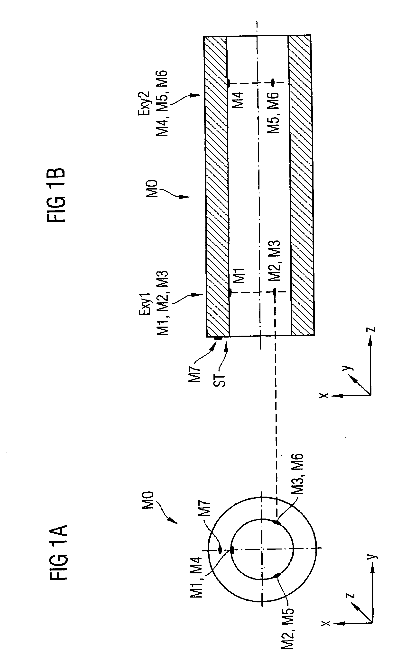
[0019]FIGS. 1A and 1B show reference points M1 through M7 used in the inventive arrangement that can be used for a position determination.

[0020]FIG. 1A shows a frontal view of a test item or, respectively, measurement object MO (here a gradient coil) whose magnetic field should be measured. FIG. 1B shows a side view of the measurement object MO in a section presentation.

[0021]In total three reference points M1, M2 and M3 lie inside the measurement object MO in a first plane Exy1 that is defined by the coordinate axes x and y. The first plane Exy1 is preferably located in the starting region of the cylindrical measurement object MO.

[0022]In total three reference points M4, M5 and M6 lie inside the measurement object in a second plane Exy2 that is defined by the coordinate axes x and y. The second plane Exy2 is preferably located in the end region of the cylindrical measurement object MO.

[0023]A seventh reference point M7 is arranged on a facing side ST of the measurement object MO.

[0...


PUM


Abstract

The invention concerns an arrangement for magnetic field measurement of a measurement object (in particular a gradient coil in a magnetic resonance apparatus) with a magnetic field sensor that is designed to measure a magnetic field of the measurement object and with a measurement mechanism on which the magnetic field sensor is arranged at a first position. The measurement object has detectable reference points that can be used for calibration of a spatial position of a position sensor. The calibrated position sensor is arranged at a second position of the measurement mechanism, such that, with the first position and the second position, a spatial position relative to the measurement object can be associated with each magnetic field strength that is measured by the magnetic field sensor.

Description

BACKGROUND OF THE INVENTION[0001]1. Field of the Invention[0002]The present invention concerns an arrangement for magnetic field measurement of a measurement object, in particular of a gradient coil of a magnetic resonance apparatus.[0003]2. Description of the Prior Art[0004]To measure magnetic fields of a measurement object (for example of a gradient coil of a magnetic resonance apparatus) a measurement mechanism is used that is moved within the gradient coil in order to examine a generally cuboid measurement volume.[0005]A magnetic field sensor is attached to the measurement mechanism for magnetic field measurement. The magnetic field sensor and the (generally cylindrical) gradient coil to be examined are mechanically aligned relative to one another.[0006]The measurement mechanism exhibits a docking plate that is movable with a support rod within the measurement volume and that has a magnetic field sensor attached at a front side thereof via a screw connection.[0007]The alignment ...

Claims


Application Information

Patent Timeline
Patent Type & Authority Patents(United States)
IPC IPC(8): G01V3/00
CPCG01R33/022
Inventor FATH, SASCHAGRANZER, ALEXANDER
Owner SIEMENS HEALTHCARE GMBH
Why Eureka
Try Eureka