
Trending system and method using window filtering

a trending system and window filtering technology, applied in the field of trending systems for physical systems, can solve the problems of increasing the need for automatic prognosis and fault detection systems, increasing the limitations of current trending systems, and exceeding complexity of modern physical systems

Active Publication Date: 2009-08-25
HONEYWELL INT INC
View PDF37 Cites 45 Cited by
  • Summary
  • Abstract
  • Description
  • Claims
  • Application Information

AI Technical Summary

Benefits of technology

The system enhances accuracy and reliability in predicting future trends and detecting faults, reducing the likelihood of unexpected failures by providing a robust and adaptive method for data filtering and trend analysis.

Problems solved by technology

Modern physical systems can be exceedingly complex.
The complexities of modern systems have led to increasing needs for automated prognosis and fault detection systems.
Unfortunately, these current trending systems suffered from many limitations.
One particular limitation in Kalman filters is that Kalman filters have typically relied upon certain statistical assumptions.
These statistical assumptions may not be valid for some applications.
Thus, Kalman filters may not be reasonably applicable to these problems.
Another limitation in these current trending systems such as Kalman filters is a lack of accuracy.
Thus, these trending systems are unable to accurately determine current sensor values or predict likely future values.
This lack of accuracy limits the effectiveness of the prognosis and fault detection system, resulting in potentially unexpected faults and / or false detection of future faults.
However, these methods generally need careful tuning to the problem at hand.
Furthermore, they do not generally provide a quantitative estimate of the reliability of their predictions.

Method used


Image

  • Trending system and method using window filtering
  • Trending system and method using window filtering
  • Trending system and method using window filtering

Examples


Embodiment Construction

[0019]The present invention provides a trending system and method for trending data in a mechanical system. The trending system receives data from the mechanical system and generates a smoothed estimated trend for the data set. This estimated trend can then be used to more accurately determine the performance of the mechanical system and prognosticate future performance.

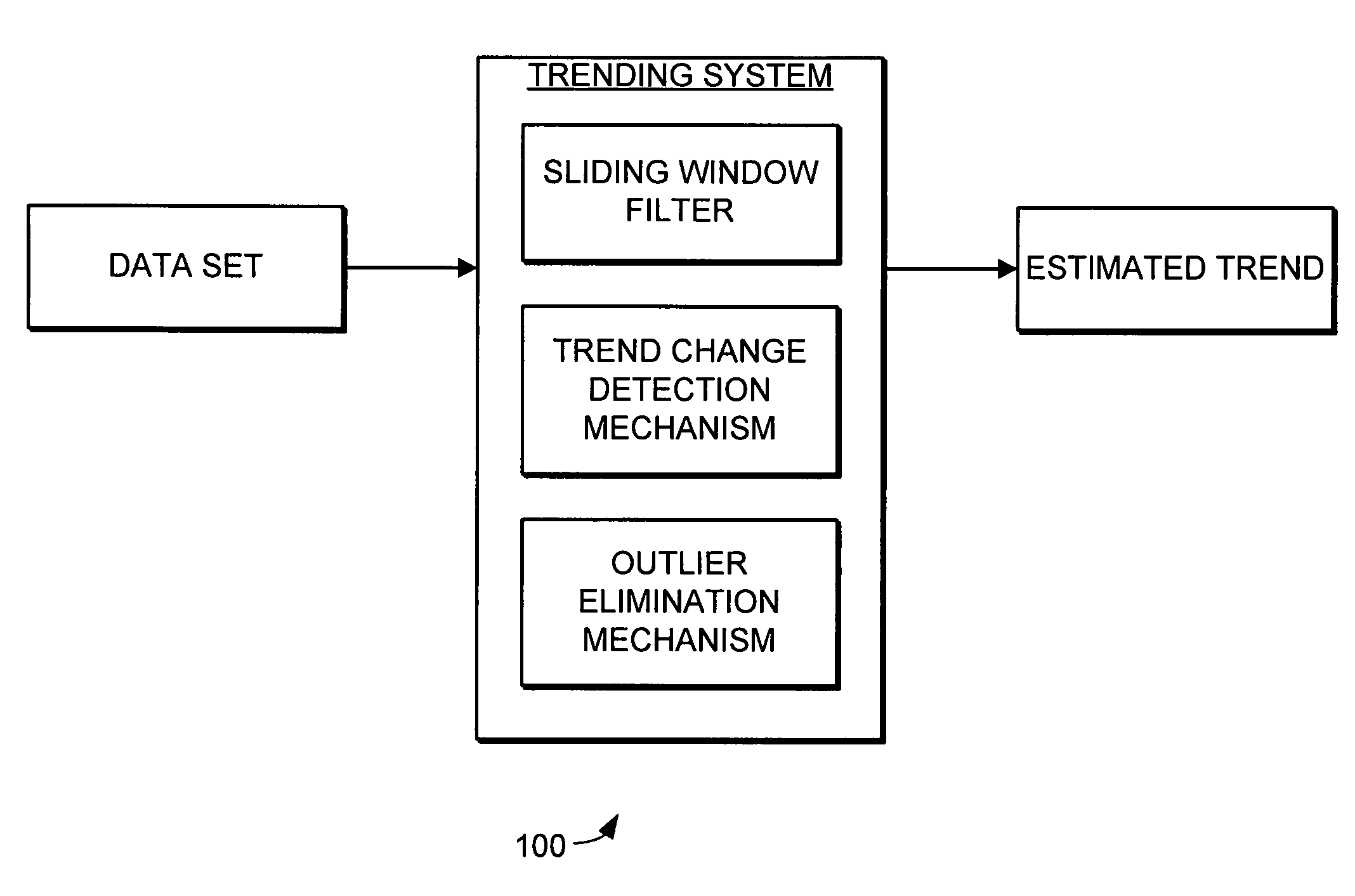
[0020]Turning now to FIG. 1, a trending system 100 is illustrated schematically. The trending system 100 includes a sliding window filter, a trend change detection mechanism, and an outlier elimination mechanism. The sliding window filter receives a data set of data points generated by the mechanical system. The sliding window filter partitions the data set using a plurality of data windows, and uses the data windows to calculate upper and lower confidence bounds for the data set. Specifically, the sliding window filter calculates upper confidence bounds and lower confidence bounds for each data point using each of t...


PUM


Abstract

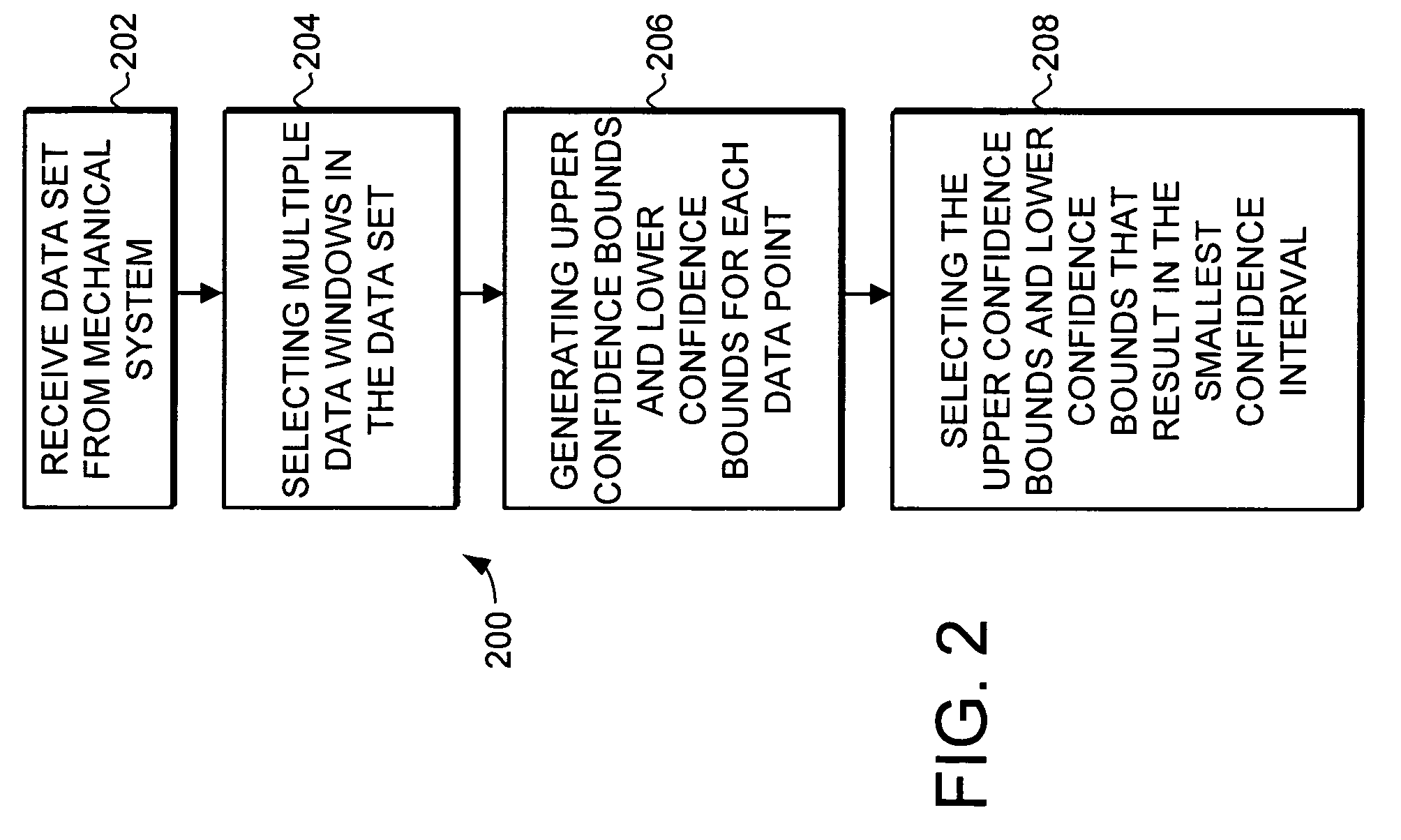
A trending system and method for trending data in a mechanical system is provided. The trending system includes a sliding window filter. The sliding window filter receives a data set of data points generated by the mechanical system. The sliding window filter partitions the data set into a plurality of data windows, and uses the data windows to calculate upper and lower confidence bounds for the data set. Specifically, the sliding window filter calculates an upper confidence bounds and lower confidence bounds for each data point using each of the multiple data windows that includes the data point. The sliding window filter then selects the upper confidence bounds and the lower confidence bounds that results in the smallest mean prediction confidence interval for that data point. This results in a smoothed estimated trend for the data set that can be used for prognostication and fault detection.

Description

FIELD OF THE INVENTION[0001]This invention generally relates to diagnostic systems, and more specifically relates to trending systems for physical systems.BACKGROUND OF THE INVENTION[0002]Modern physical systems can be exceedingly complex. The complexities of modern systems have led to increasing needs for automated prognosis and fault detection systems. These prognosis and fault detection systems are designed to monitor the system in an effort to predict the future performance of the system and detect potential faults. These systems are designed to detect these potential faults such that the potential faults can be addressed before the potential faults lead to failure in the system.[0003]Physical systems include a variety of mechanical and electrical systems. One type of system where prognosis and fault detection is of particular importance is aircraft systems. In aircraft systems, prognosis and fault detection can detect potential faults such that they can be addressed before they...

Claims


Application Information

Patent Timeline
Patent Type & Authority Patents(United States)
IPC IPC(8): G06F15/00H04B17/00G05B23/02
CPCG05B23/0232
Inventor ARIYUR, KARTIK B.JELINEK, JAN
Owner HONEYWELL INT INC
Learn More