Automatic air-feeding mechanism for pneumatic tire

a pneumatic tire and automatic technology, applied in the direction of positive displacement liquid engines, pumping machines, machines/engines, etc., can solve the problems of affecting the ride quality or handling, requiring considerable force it is difficult for a person without much strength to operate air pumps, etc., to reduce the resistance to the rotation of the wheel body and reduce the force. , the effect of small for

Inactive Publication Date: 2009-09-01
NAKANO TAKAJI
View PDF25 Cites 52 Cited by
  • Summary
  • Abstract
  • Description
  • Claims
  • Application Information

AI Technical Summary

Benefits of technology

[0007]Another object of the present invention is to provide an automatic air-feeding mechanism for a pneumatic tire which can produce a large amount of compressed air with a small number of rotations of the wheel body and with a small force.
[0008]Another object of the present invention is to provide an automatic air-feeding mechanism for a pneumatic tire which can produce a sufficient amount of compressed air in a short travel distance so that it can supply compressed air to a pneumatic tire of a vehicle which is driven too short a distance to rotate a wheel a sufficient number of times during normal use such as a wheelchair.
[0009]Another object of the present invention is to provide an automatic air-feeding mechanism for a pneumatic tire which can produce a large amount of compressed air with a small number of rotations of the wheel body with a small force and which can supply compressed air to a pneumatic tire and a part of the vehicle other than the pneumatic tire when the vehicle is running.
[0010]Another object of the present invention is to provide an automatic air-feeding mechanism for a pneumatic tire which can reduce the resistance to the rotation of the wheel body about the axle.

Problems solved by technology

When the air pressure is too low, it adversely affects the ride quality or handling.
However, a considerable force is required to operate an air pump to feed air into a pneumatic tire.
Thus, it is difficult for a person without much strength to operate an air pump to feed air into a pneumatic tire.

Method used


Image

  • Automatic air-feeding mechanism for pneumatic tire
  • Automatic air-feeding mechanism for pneumatic tire
  • Automatic air-feeding mechanism for pneumatic tire

Examples


first embodiment

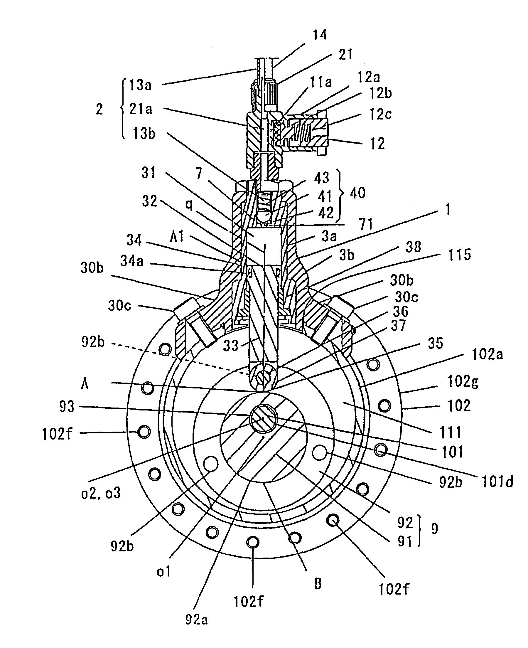
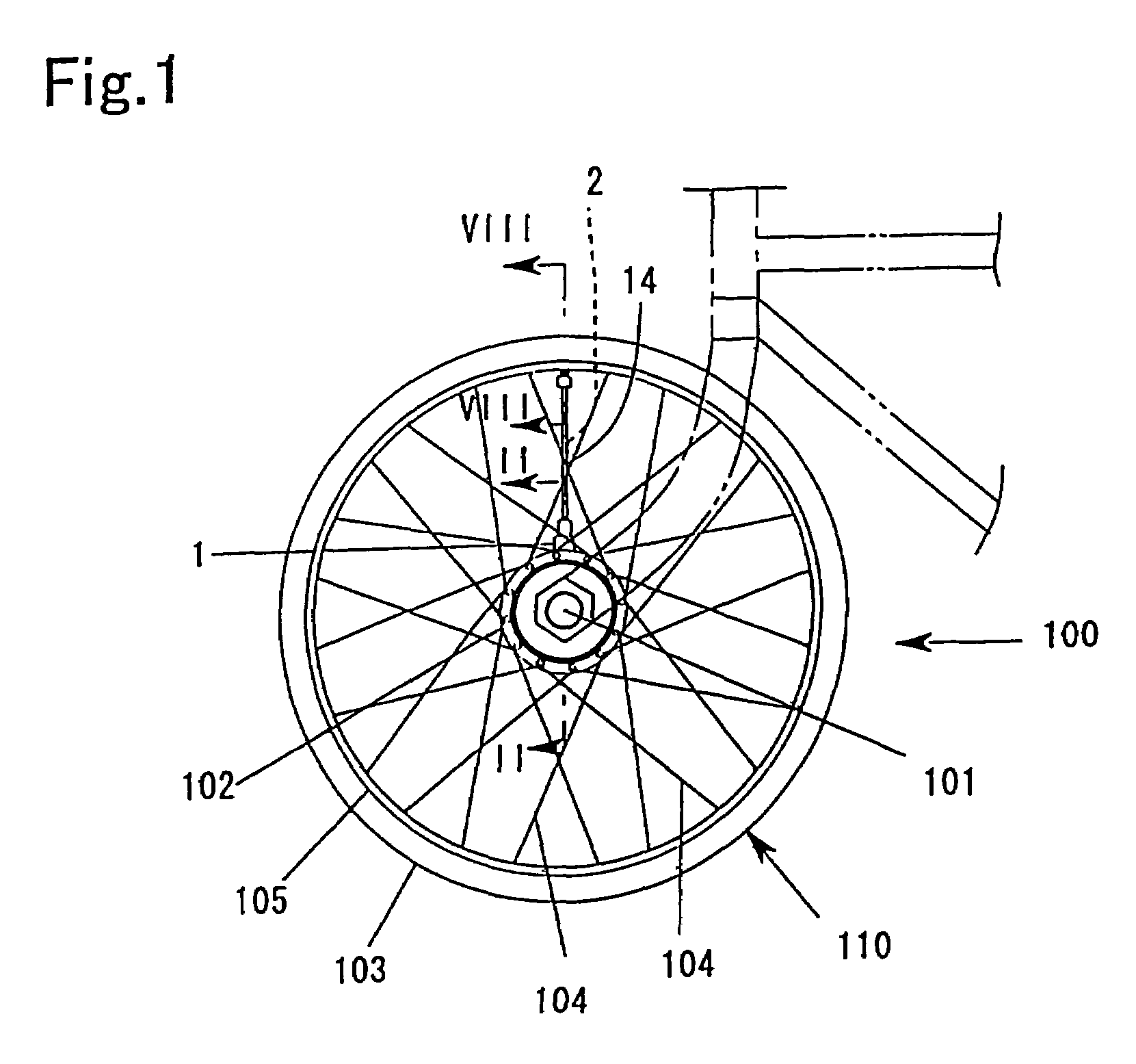
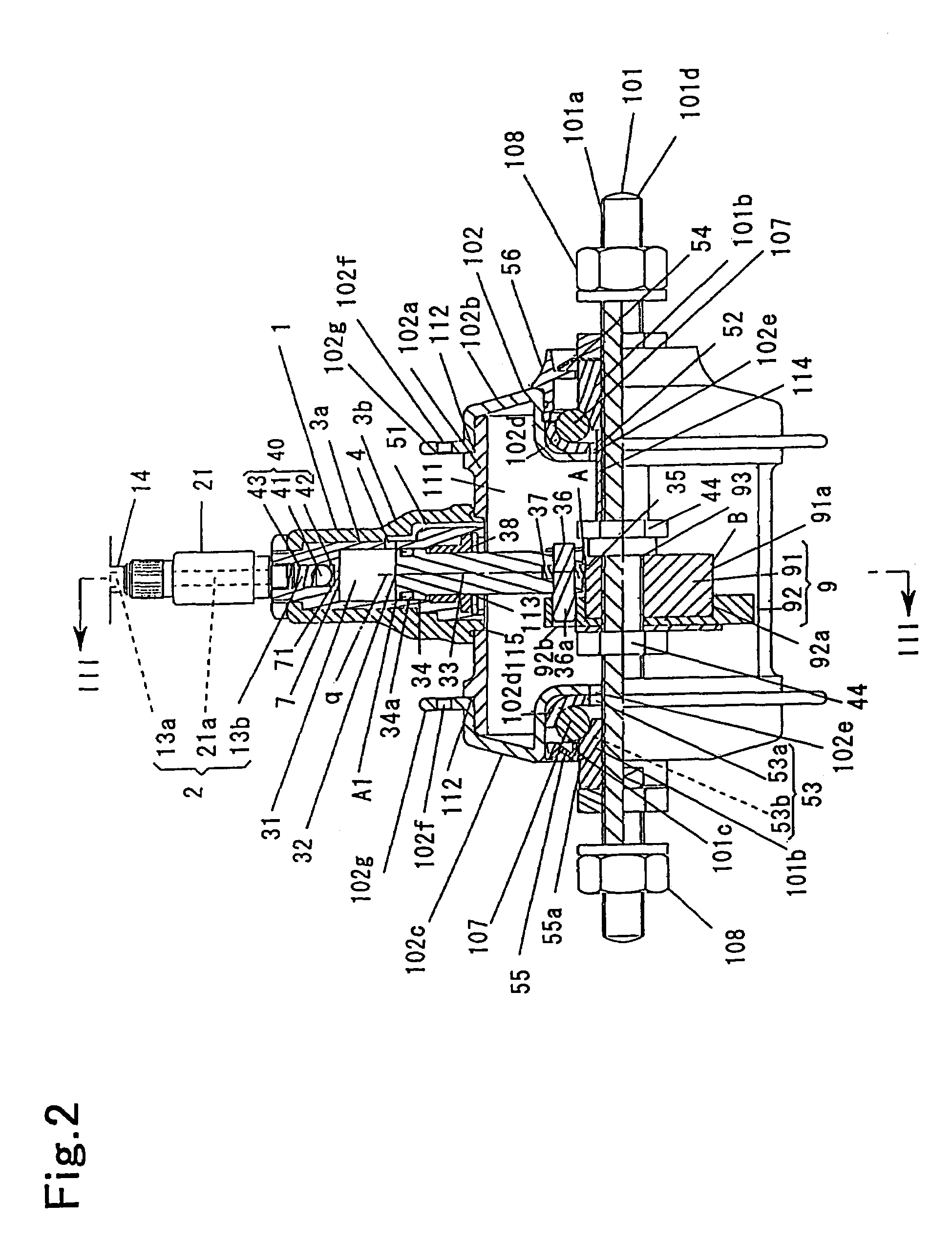
[0043]Description will be hereinafter made of the embodiments of the present invention in detail with reference to the drawings. FIG. 1 is a side view of a wheel of a bicycle provided with an automatic air-feeding mechanism for a pneumatic tire according to the present invention, FIG. 2 is an enlarged cross-sectional explanatory view taken along the line II-II in FIG. 1, and FIG. 3 is a cross-sectional explanatory view taken along the line III-III in FIG. 2.

[0044]In this embodiment, the automatic air-feeding mechanism for a pneumatic tire is provided on a front wheel 100 of a bicycle. The wheel 100 of the bicycle provided with the automatic air-feeding mechanism for a pneumatic tire has an axle 101 and a wheel body 110 rotatable about the axle 101.

[0045]As shown in FIG. 2, the axle 101 has an axle body 101d having threads 101a on its outer periphery, ball pushers 101b and 101b threaded on both right and left sides of the axle body 101d and secured thereto, and a pipe-like positionin...

second embodiment

[0134]The automatic air-feeding mechanism of the second embodiment is provided on both a left wheel 500 and a right wheel (not shown) of a wheelchair to constitute an automatic air-feeding mechanism for pneumatic tires of a wheelchair. The left wheel 500 and the right wheel of the wheelchair provided with the automatic air-feeding mechanism for pneumatic tires of a wheelchair are the same in construction. Description will be made of the left wheel 500 and description of the right wheel will be omitted.

[0135]The left wheel 500 has an axle 101 and a wheel body 110. The axle 101 is the same in construction as the axle 101 in the first embodiment.

[0136]As shown in FIG. 9, the wheel body 110 has a hub 102, a pneumatic tire 103 and an automatic air-feeding mechanism. The hub 102 and the pneumatic tire 103 are the same in construction as the hub 102 and the pneumatic tire 103 in the first embodiment.

[0137]The automatic air-feeding mechanism has a plurality of compressed air producing secti...

third embodiment

[0176]In the third embodiment, the axle 201 has an axial hole 43a as shown in FIG. 19. The axial hole 43a extends in the axle 201 along the axis thereof from the left end to a point slightly on the left of the center thereof. That is, the axial hole 43a extends from the outside of the hub 102 attached to the axle 201 to the inside thereof. The bottom of the axial hole 43a extended into the hub 202 is communicated with the outside of the axle 201 via through holes 43b and 43b extending from the axial hole 43a to the outer periphery of the axle 201 as shown in FIG. 21.

[0177]The hub 102 of the wheel body and the pneumatic tire 103 are generally the same in construction as the hub 102 and the pneumatic tire 103 of the first embodiment.

[0178]The automatic air-feeding mechanism has a pneumatic tire compressed air supply passage 20a for introducing compressed air produced in the first compressed air producing section 10a to the pneumatic tire 103 and an another part compressed air supply p...


PUM


Abstract

To provide an automatic air-feeding mechanisms which can produce a large amount of compressed air with a small number of rotations of a wheel body and with a small force. The automatic air-feeding mechanisms has first and second compressed air producing sections 1a and 1b, and pneumatic tire compressed air supply passages 2a and 2b for introducing the compressed air produced in the compression air producing sections to a pneumatic tire. The first and second compressed air producing sections 1a and 1b are attached to a hub drum 102a of the hub 102 at positions 180° apart from each other. When the wheel body is rotated, the first and second compressed air producing sections 1a and 1b alternately produce compressed air.

Description

CROSS REFERENCE TO RELATED APPLICATIONS[0001]The disclosure of Japanese Patent Application No. 2003-090079 (filed on Mar. 28, 2003) and International Application No. PCT / JP / 2003 / 015820 (filed on Dec. 10, 2003) including the specification, claims, drawings and abstract are incorporated herein by reference in its entirety.TECHNICAL FIELD[0002]The present invention relates to an automatic air-feeding mechanism for a pneumatic tire which can produce compressed air and supply it to the pneumatic tire when a wheel body is rotated about an axle.BACKGROUND ART[0003]Pneumatic tires holding air are mounted on wheels of automobiles or bicycles. Even if air is pumped into such a pneumatic tire until the air pressure therein reaches a specific level, the air gradually escapes therefrom and the air pressure therein gradually decreases over time. When the air pressure is too low, it adversely affects the ride quality or handling. Thus, when the air pressure becomes much lower than the a specific l...

Claims


Application Information

Patent Timeline
Patent Type & Authority Patents(United States)
IPC IPC(8): B60C23/10B60C29/00F04B17/06B60C23/12
CPCB60C23/12B60C23/127B60C23/137
Inventor NAKANO, TAKAJI
Owner NAKANO TAKAJI
Why Eureka
Try Eureka