Vehicular control device

a technology of control device and control device, which is applied in the direction of engine-driven generators, machine/engine, process and machine control, etc., can solve the problems of not being able to achieve acceleration as desired and providing increased driving force, and achieve the effect of improving acceleratability

Inactive Publication Date: 2009-09-01
TOYOTA JIDOSHA KK
View PDF51 Cites 2 Cited by
  • Summary
  • Abstract
  • Description
  • Claims
  • Application Information

AI Technical Summary

Benefits of technology

[0006]The present invention has been made to overcome the above disadvantage and it contemplates a vehicular control device that allows a vehicle to be improved in acceleratability.
[0007]The present control device for a vehicle includes: an engine; a first rotating electric machine coupled to the engine; a second rotating electric machine coupled to the engine; a battery; a capacitor provided electrically in parallel with the battery; and a control unit causing the battery and the capacitor to supply power to increase a number of rotations of the second rotating electric machine and also controlling the first rotating electric machine and the second rotating electric machine to prevent the first rotating electric machine from acting as a load of the engine when the vehicle is accelerated as a driving force of the engine is transmitted to a driving wheel.
[0008]In accordance with the present invention, in accelerating a vehicle when the engine's motive power is being transmitted to a driving wheel a battery and a capacitor supply a second rotating electric machine with electric power to increase the number of rotations of the second rotating electric machine. As the battery and the capacitor supply the second rotating electric machine with electric power the second rotating electric machine can be supplied with sufficient electric power. In particular, the capacitor is excellent in instant output, and can supply the second rotating electric machine with electric power with fast responsiveness. The second rotating electric machine can thus provide a driving force to accelerate the vehicle. The first rotating electric machine is controlled so that it does not act as a load of the engine. This allows the engine to provide a rapidly increased number of rotations. The engine and the second rotating electric machine can thus provide driving force to accelerate the vehicle. Consequently a control device for a vehicle can be provided that can improve the vehicle in acceleratability.

Problems solved by technology

As such, when the vehicle is accelerated, the engine cannot provide increased driving force, and as a result, acceleration as desired may not be obtained.

Method used


Image

  • Vehicular control device
  • Vehicular control device
  • Vehicular control device

Examples


Embodiment Construction

[0024]Hereinafter reference will be made to the drawings to describe an embodiment of the present invention. In the following description, identical components are denoted by identical reference characters. Their names and functions are also identical. Accordingly they will not be described repeatedly.

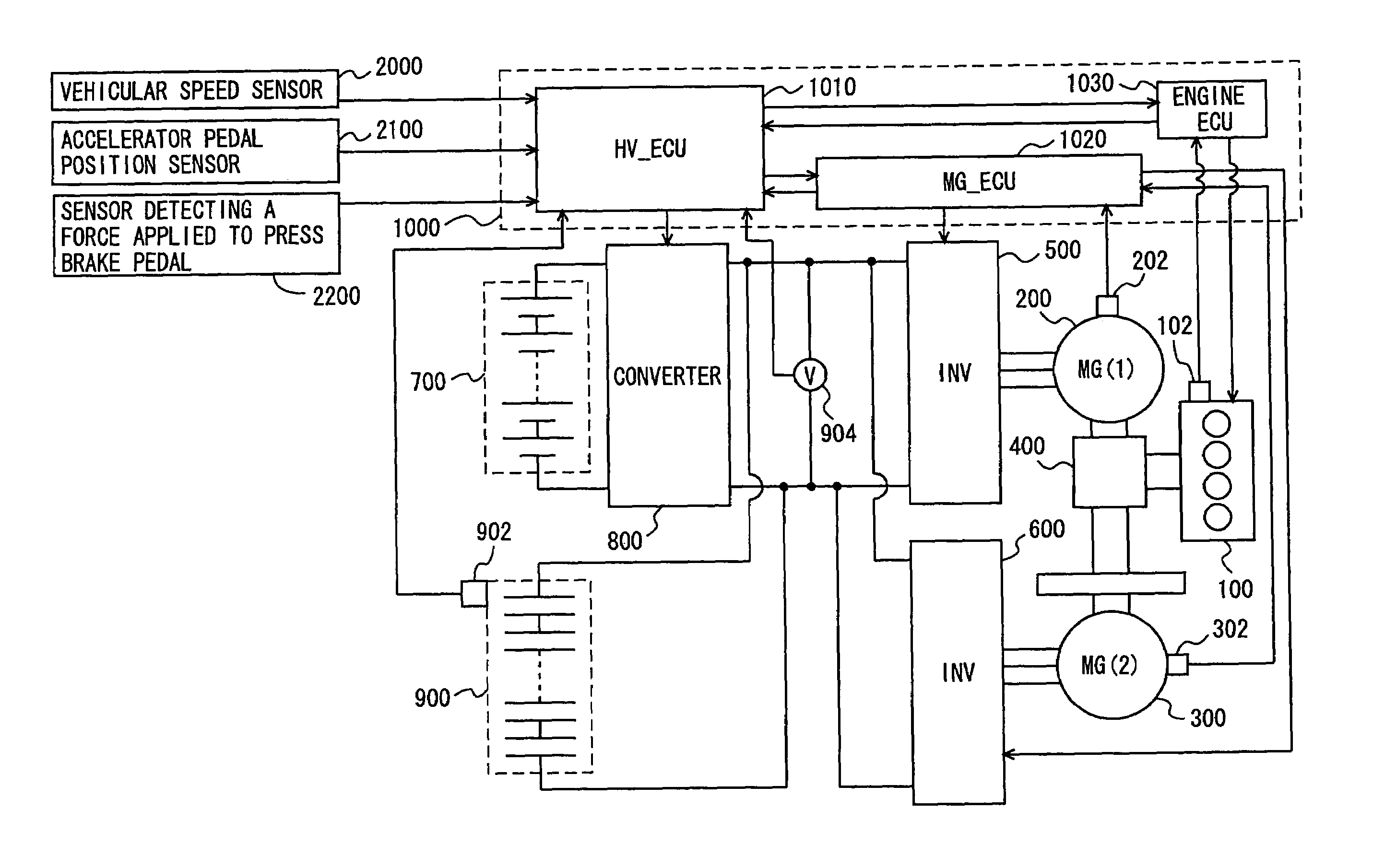
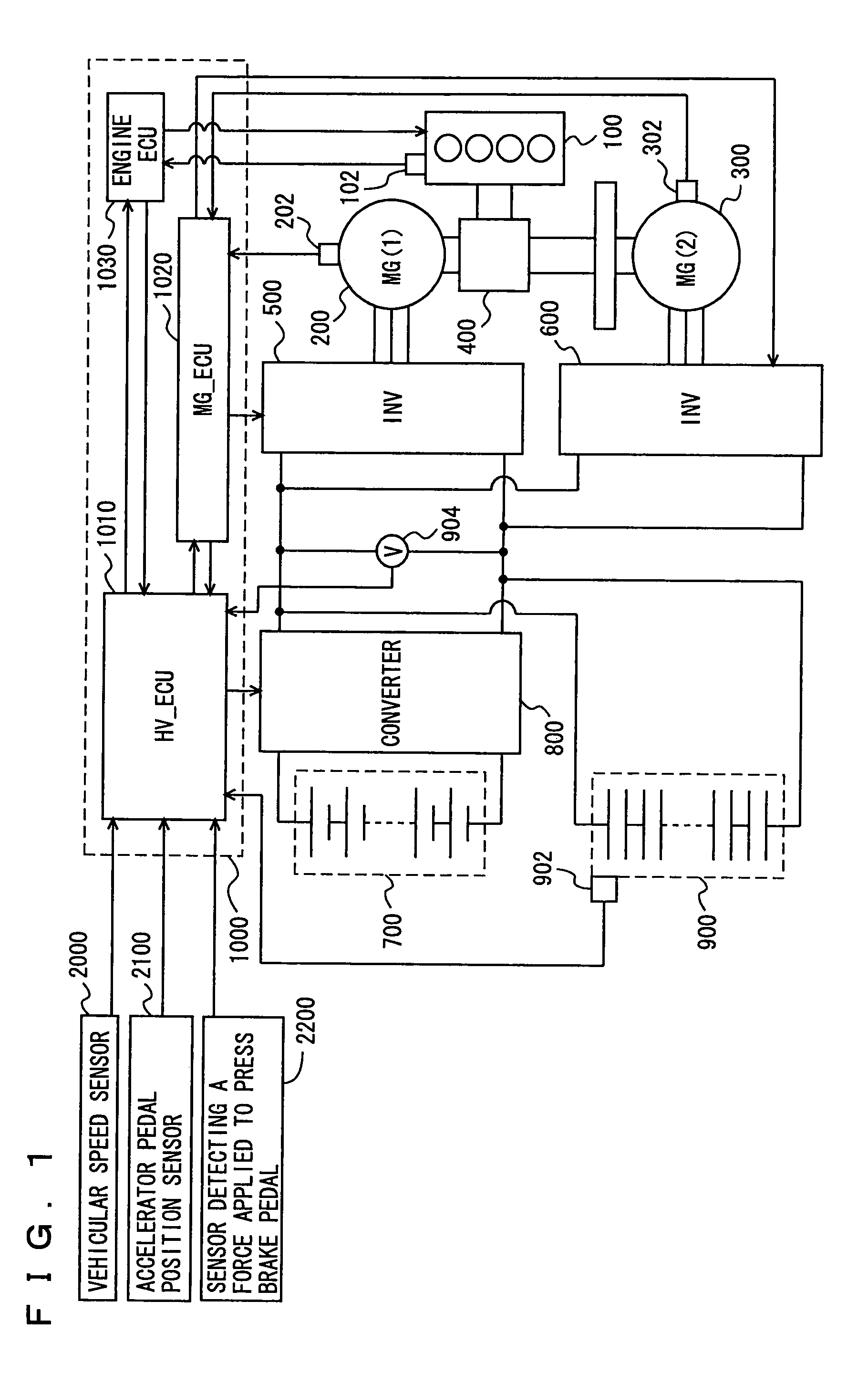
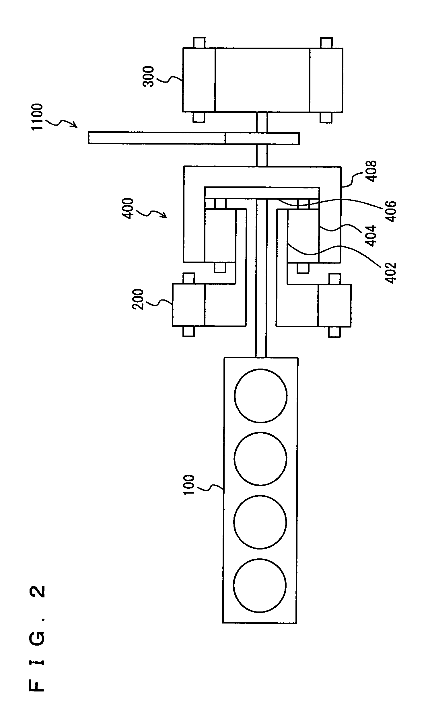
[0025]With reference to FIG. 1, the present embodiment provides a control device mounded in a hybrid vehicle as will be described hereinafter. The vehicle includes an engine 100, motor generators (MGs)(1) 200 and (2) 300, a power split device 400, inverters (1) 500 and (2) 600, a battery 700, a converter 800, and a capacitor 900. The vehicle is run by a driving force received from at least one of engine 100 and MG(2) 300.

[0026]Engine 100 and MGs(1) 200 and (2) 300 are connected via power split device 400. Engine 100 generates motive power, which is split by power split device 400 into two routes. One route is that driving a wheel (not shown) via a reducer. The other route is that drivi...


PUM


Abstract

An ECU executes a program including the steps of: if an accelerator pedal position P is larger than a predetermined accelerator pedal position, calculating an output that an MG(2) is required to provide; calculating an output that a capacitor and a battery can supply; calculating an output that can be supplied to MG(1), by subtracting the output that the MG(2) is required to provide from the output that the capacitor and the battery can supply; calculating a torque that each MG is instructed to output, as based on the output that can be supplied to MG(1) and the output that an MG(2) is required to provide; and controlling inverters (1) and (2), as based on the torque that each MG is instructed to output, to accelerate the vehicle.

Description

TECHNICAL FIELD[0001]The present invention relates generally to vehicular control devices and particularly to the technology applied to control hybrid vehicles capable of running by a driving force received from a rotating electric machine as well as that received from an engine.BACKGROUND ART[0002]In recent years, as part of an approach to address environmental issues, a hybrid vehicle capable of running by a driving force received from a rotating electric machine is increasingly gaining attention. When such hybrid vehicle is to be accelerated, it utilizes a driving force received from the engine to gain acceleration, generate power supplied to the rotating electric machine, and the like. Accordingly it requires a rapidly increased number of rotations of the engine.[0003]Japanese Patent Laying-open No. 10-238380 discloses a control device for a hybrid vehicle that allows improved responsiveness of its engine in a transient operation of the vehicle. More specifically, as described i...

Claims


Application Information

Patent Timeline
Patent Type & Authority Patents(United States)
IPC IPC(8): B60K6/20B60K6/365B60K6/445B60L50/16B60L50/15B60W10/06B60W10/08B60W10/26B60W20/00F02D29/02F02D29/06
CPCB60K6/445B60W10/04B60W10/08B60W10/26B60W20/00F02D29/02F02D29/06B60L11/123B60L11/14B60L11/1864B60K6/448B60L2240/423B60L2240/486B60W50/0098B60W2540/10B60W2710/083B60W2710/105Y02T10/6243Y02T10/642Y02T10/6239Y10S903/91B60L2210/10B60L2210/40B60L2240/12B60L2250/26Y02T10/7077Y02T10/7005Y02T10/7241Y02T10/7061Y02T10/7216Y02T10/6217B60L50/61B60L50/16B60L58/21Y02T10/62Y02T10/64Y02T10/70Y02T10/72Y02T10/7072
Inventor ISHIKAWA, TETSUHIROYOSHIDA, HIROSHI
Owner TOYOTA JIDOSHA KK
Why Eureka
Try Eureka