Unlock instant, AI-driven research and patent intelligence for your innovation.

Multi-chip PWM synchronization and communication

a multi-chip, synchronization and communication technology, applied in the field of audio amplification systems, can solve the problems of low performance applications, complex and costly applications to implement, and the inability to accept solutions widely

Active Publication Date: 2009-09-01
INTERSIL INC
View PDF11 Cites 3 Cited by
  • Summary
  • Abstract
  • Description
  • Claims
  • Application Information

AI Technical Summary

Benefits of technology

[0011]One or more of the problems outlined above may be solved by the various embodiments of the invention. Broadly speaking, the invention comprises systems and methods for enabling the use of multiple digital PWM chips in the same system to provide the additional channels and correspondi

Problems solved by technology

More particularly, these attempts utilized analog modulation schemes that resulted in very low performance applications.
These applications were very complex and costly to implement.
Consequently, these solutions were not widely accepted.
Class D technology was therefore unable to displace legacy Class AB amplifiers in mainstream amplifier applications.
These digital PWM schemes, however, did little to offset the major barriers to integration of PWM modulators into the total amplifier solution.
Class D technology has therefore continued to be unable to displace legacy Class AB amplifiers in mainstream applications.
There are a number of problems with existing digital PWM modulation schemes.
One of the problems is that audio system implementations are requiring increasing numbers of channels.
While it is possible to provide additional channels on a single chip, this typically is not a practical solution for several reasons.
For example, there simply may not be enough space on the chip to implement the additional channels.
It may also be possible that there are not enough resources (e.g., processor cycles) to process all of the channels on the same chip.
Further, the complexity of the design may increase dramatically with the additional channels.
Still further, even if a few additional channels could be accommodated, such a solution would not address the next generation of system requirements in which still more channels were required.
Existing digital PWM systems are not implemented across multiple chips because of difficulties that are associated with the interaction of multiple chips.
One such difficulty may be the problem of synchronization.
No such mechanism currently exists for digital PWM audio amplification systems.

Method used


Image

  • Multi-chip PWM synchronization and communication
  • Multi-chip PWM synchronization and communication
  • Multi-chip PWM synchronization and communication

Examples


Embodiment Construction

[0020]One or more embodiments of the invention are described below. It should be noted that these and any other embodiments described below are exemplary and are intended to be illustrative of the invention rather than limiting.

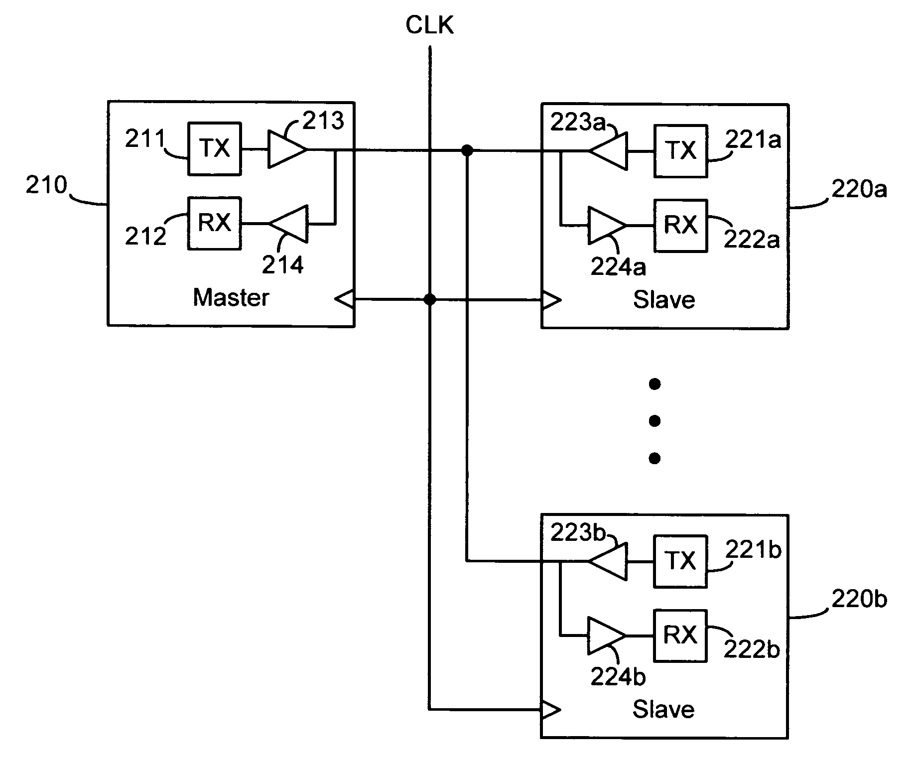
[0021]As described herein, various embodiments of the invention comprise systems and methods for synchronizing multiple digital audio controller chips (i.e., controllers implemented on different pieces of silicon, so that they cannot be internally synchronized). In one embodiment, one of the chips is designated as a master, while the other chips are designated as slaves. A common line connects all of the chips and is used to transmit synchronization signals from the master to the slaves. When the master chip transmits an appropriate signal, all of the chips simultaneously begin operation. As noted above, “synchronized operation” in this context refers to the chips beginning to operate and doing so in a synchronized manner, but other embodiments may use the sa...


PUM


Abstract

Systems and methods for synchronizing multiple digital audio controller chips, wherein one of the chips is designated as a master and the other chips are designated as slaves. A common line connects all of the chips and is used to transmit synchronization signals from the master to the slaves. Each of the chips listens for an appropriate signal and, when the signal is detected, all of the chips simultaneously begin operation. In one embodiment, the synchronization signal comprises a transition on the shared line to an active state. The transition is repeated at fixed intervals and maintained in the active state for a fixed period in order to enable the chips to determine whether synchronization is being maintained. The signal may be sampled and / or filtered to improve reliability. The chips may be able to drive the shared line active to indicate that synchronization has been lost.

Description

RELATED APPLICATIONS[0001]This application claims priority to: U.S. Provisional Patent Application No. 60 / 469,734, entitled “Multi-chip PWM with Staggered Outputs,” by Jack B. Andersen, et al., filed May 12, 2003; U.S. Provisional Patent Application No. 60 / 456,414, entitled “Adaptive Anti-Clipping Protection,” by Taylor, et al., filed Mar. 21, 2003; U.S. Provisional Patent Application No. 60 / 456,430, entitled “Frequency Response Correction,” by Taylor, et al., filed Mar. 21, 2003; U.S. Provisional Patent Application No. 60 / 456,429, entitled “High-efficiency, High-Performance Sample Rate Converter,” by Andersen, et al., filed Mar. 21, 2003; U.S. Provisional Patent Application No. 60 / 456,421, entitled “Output Device Switch Timing Correction,” by Taylor, et al., filed Mar. 21, 2003; U.S. Provisional Patent Application No. 60 / 456,422, entitled “Output Filter, Phase Timing Correction,” by Taylor, et al., filed Mar 21, 2003; U.S. Provisional Patent Application No. 60 / 456,428, entitled “Ou...

Claims


Application Information

Patent Timeline
IPC IPC(8): G06F17/00H03F1/52H03F3/217H03G7/00H04L7/02
CPCH03F1/523H03F3/2171H03F3/2175H04L7/005H03G7/007H04L7/02H03F2200/331
Inventor ANDERSEN, JACK B.CHIENG, DANIEL L. W.KOST, MICHAEL A.LARSON, JAN A.
Owner INTERSIL INC