Gravity gradiometer

a gravity gradiometer and gradiometer technology, applied in the field of gravity gradiometers, can solve the problems of noise or swamp, oscillation of both sensor masses, etc., and achieve the effect of reducing the influence of external angular acceleration on the rotation of the housing

Inactive Publication Date: 2009-09-08
TECH RESOURCES PTY LTD
View PDF97 Cites 28 Cited by
  • Summary
  • Abstract
  • Description
  • Claims
  • Application Information

AI Technical Summary

Benefits of technology

[0016]wherein the gravity gradiometer is arranged so that an influence of an external angular acceleration on the rotation of the housing is reduced by the actuator when the transducer generates a transducer signal effected by the external angular acceleration on the gravity gradiometer.
[0019]In one specific embodiment of the present invention the gimballed support structure is triaxial and comprises three substantially orthogonal axes. In this embodiment the gimballed support structure comprises at least two additional actuators arranged for rotating the housing about each of the three substantially orthogonal axes. Further, the gimballed support structure may comprise gyroscopes that detect rotation about respective axes and that are coupled to respective actuators in a manner such that the actuators correct for rotation generated by the external angular acceleration. In this embodiment the electrical feedback loop is arranged so that the electrical signal, being associated with the transducer signal, is used to further reduce the influence of the external angular acceleration. In one specific embodiment the electrical feedback loop is arranged so that rotation of the housing about the z-axis is fine-tuned and influence of the external angular acceleration on the rotation about the z-axis is substantially avoided.

Problems solved by technology

This creates accelerations of the gradiometer which are detected by the gravity gradiometer and if not compensated for, will produce noise or swamp actual accelerations or movement of the gradiometer in response to the gravity gradient which is to be detected by the gravity gradiometer.
For measurement of the gravity gradient the instrument is continuously rotated and a local change in the gravity gradient results in oscillating of both sensor masses relative to a rotated housing of the instrument.

Method used


Image

  • Gravity gradiometer
  • Gravity gradiometer
  • Gravity gradiometer

Examples


Embodiment Construction

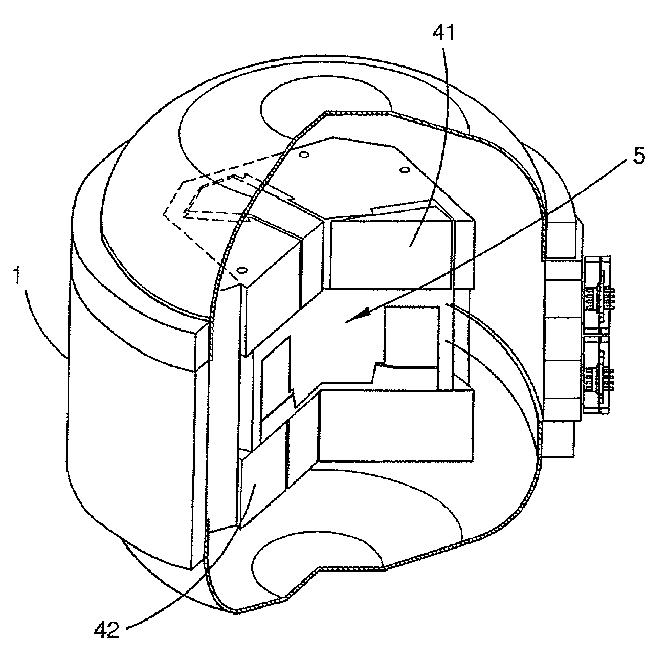
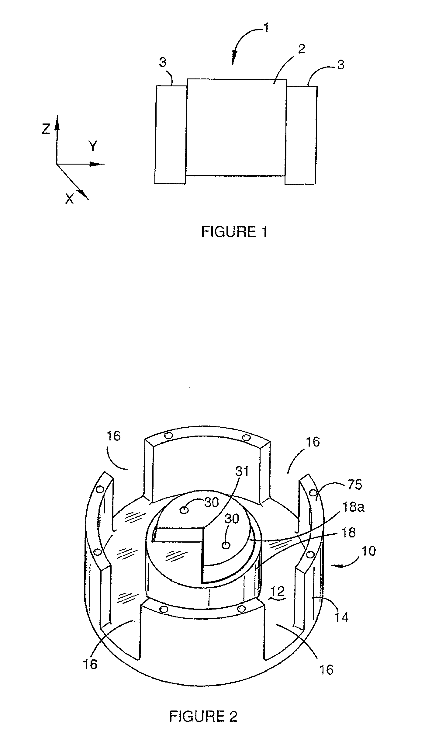
[0053]FIG. 1 is a schematic view of a gravity gradiometer 1 according to a specific embodiment of the present invention. The gravity gradiometer 1 is arranged for vertical positioning relative to a ground plane. Throughout this specification the ground plane coincides with an x-y plane of an x,y,z-coordination system and consequently the gravity gradiometer is in this embodiment arranged for orientation along the z-axis so that the Γxy and (Γxx-Γyy) components of the gravity gradient tensor can be measured.

[0054]The function of the gravity gradiometer 1 may be briefly summarized as follows. The gravity gradiometer has in this embodiment two substantially identical sensor masses which are pivotally mounted on a mounting so that they can oscillate relative to the mounting. The sensor masses with mounting are rotated about the z-axis and with an angular frequency that approximately equals half the resonance frequency of sensor masses. A gravity gradient will result in a force on the se...


PUM


Abstract

The present invention provides a gravity gradiometer for measuring components of the gravity gradient tensor. The gravity gradiometer comprises a housing and a gimballed support structure with at least one actuator. The gravity gradiometer further comprises at least one sensor mass arranged for movement in response to a gravity gradient. The gravity gradiometer also comprises a transducer that is arranged so that the movement of the at least one sensor mass relative to a portion of the transducer generates a transducer signal. Further, the gravity gradiometer comprises an electrical feedback loop arranged to direct an electrical signal to the actuator of the external support structure. The gravity gradiometer is arranged so that an influence of an external angular acceleration on the rotation of the housing is reduced by the actuator when the transducer generates a transducer signal effected by the external angular acceleration on the gravity gradiometer.

Description

FIELD OF THE INVENTION[0001]The present invention relates to a gravity gradiometer and to components for high precision measurement instruments.BACKGROUND OF THE INVENTION[0002]Gravimeters are used in geological exploration to measure the first derivatives of the earth's gravitational field. Whilst some advances have been made in developing gravimeters which can measure the first derivatives of the earth's gravitational field because of the difficulty in distinguishing spatial variations of the field from temporal fluctuations of accelerations of a moving vehicle, these measurements can usually be made to sufficient precision for useful exploration only with land-based stationary instruments.[0003]Gravity gradiometers (as distinct from gravimeters) are used to measure the second derivative of the gravitational field and use a sensor which is required to measure the differences between gravitational forces down to one part in 1012 of normal gravity.[0004]Typically such devices have b...

Claims


Application Information

Patent Timeline
Patent Type & Authority Patents(United States)
IPC IPC(8): G01C9/14G01V7/16
CPCG01V7/08
Inventor VAN KANN, FRANK JOACHIMWINTERFLOOD, JOHN
Owner TECH RESOURCES PTY LTD
Why Eureka
Try Eureka