Tire mounter and method of mounting tire

a tire mounter and tire technology, applied in the field of tire mounters, can solve the problems of large size easy damage to the upper bead part of the tire, etc., and achieve the effect of low rigidity and high operability

Active Publication Date: 2009-09-08
HONDA LOGISTICS
View PDF11 Cites 15 Cited by
  • Summary
  • Abstract
  • Description
  • Claims
  • Application Information

AI Technical Summary

Benefits of technology

[0010]The invention has been developed from the foregoing point of view and it is an object of the invention to provide a mounter for significantly reducing friction applied to bead parts of a tire relative to a wheel to excellently prevent the tire from being damaged, and a method of mounting the tire on the wheel using this mounter.
[0018]As a result, the contact load can be significantly reduced when mounting the tire on the wheel (the maximum value of the contact value in a specific direction of three dimensional directions of x, y and z is reduced to about 20 Kg, and will be described in detail later).
[0019]In other words, the damage to the tire can be significantly reduced. As a result, a large damage prevention effect can be obtained. Abnormality of the tire which has been first found conventionally with the lapse of time after the tire is mounted on the wheel can be prevented beforehand. Further, from this fact, an overhaul for inspecting damages to the tire by sampling inspection which has been carried out conventionally after mounting the tire on the wheel is not necessary.
[0022]According to the mounter of the invention, if the bead guide plate is additionally provided with an outer diameter adjustment mechanism, it can smoothly cope with tires and wheels having various sizes. That is, it is possible to obtain a more versatile mounter.
[0024]According to the method of mounting the tire of the invention using the foregoing mounter, the lower and the upper bead parts of the tire can be mounted on the wheel by turnably driving the bead guide plate at one time. As a result, it is possible to obtain a very high operability. This one-motion mounting system is particularly useful in the case where the tire is small-sized and has low rigidity.

Problems solved by technology

Meanwhile, in the foregoing conventional case where the bead parts of the tire to be mounted are forcibly slid on the periphery (edge part) of the wheel while being compelled to contact the same, a friction force of the tire when contacting the wheel becomes considerably large and brings about a concern that the bead parts are prone to be damaged.
The inventor of this application studied this point more in detail and it was found that if the contact load is large, especially the upper bead part of the tire is prone to be damaged with ease.
The outer side of the bead part has sufficient strength since it is exposed to the outside, while the inner side of the bead part does not have sufficient strength such as the strength of the outer side of the bead part, because it is positioned inside the wheel when the tire is mounted on the wheel.
However, when the upper bead part of the tire is mounted on the wheel, an inner side of the upper bead part (part which is weak in strength) is compelled to contact the outer periphery of the wheel, the level of damage of the tire is prone to be large.
It is more troublesome that once the tire is mounted on the wheel, the level of the damage (generation of cracks and so forth) at the inner side of the bead part of the tire cannot be seen from the outside so that such damage is hardly found out and forms hidden defects.
The cracks of the tire grow with time, and it is found when abnormality occurs to the tire during the traveling of the tire.
If this interval is made large, the biting of the tire relative to the wheel becomes inferior and causes a new problem that an excellent mounting of the tire is not guaranteed.
In this case, additional steps are increased, inevitably lowering the efficiency caused by slowing down the speed when mounting the tire on the wheel.

Method used


Image

  • Tire mounter and method of mounting tire
  • Tire mounter and method of mounting tire
  • Tire mounter and method of mounting tire

Examples


Embodiment Construction

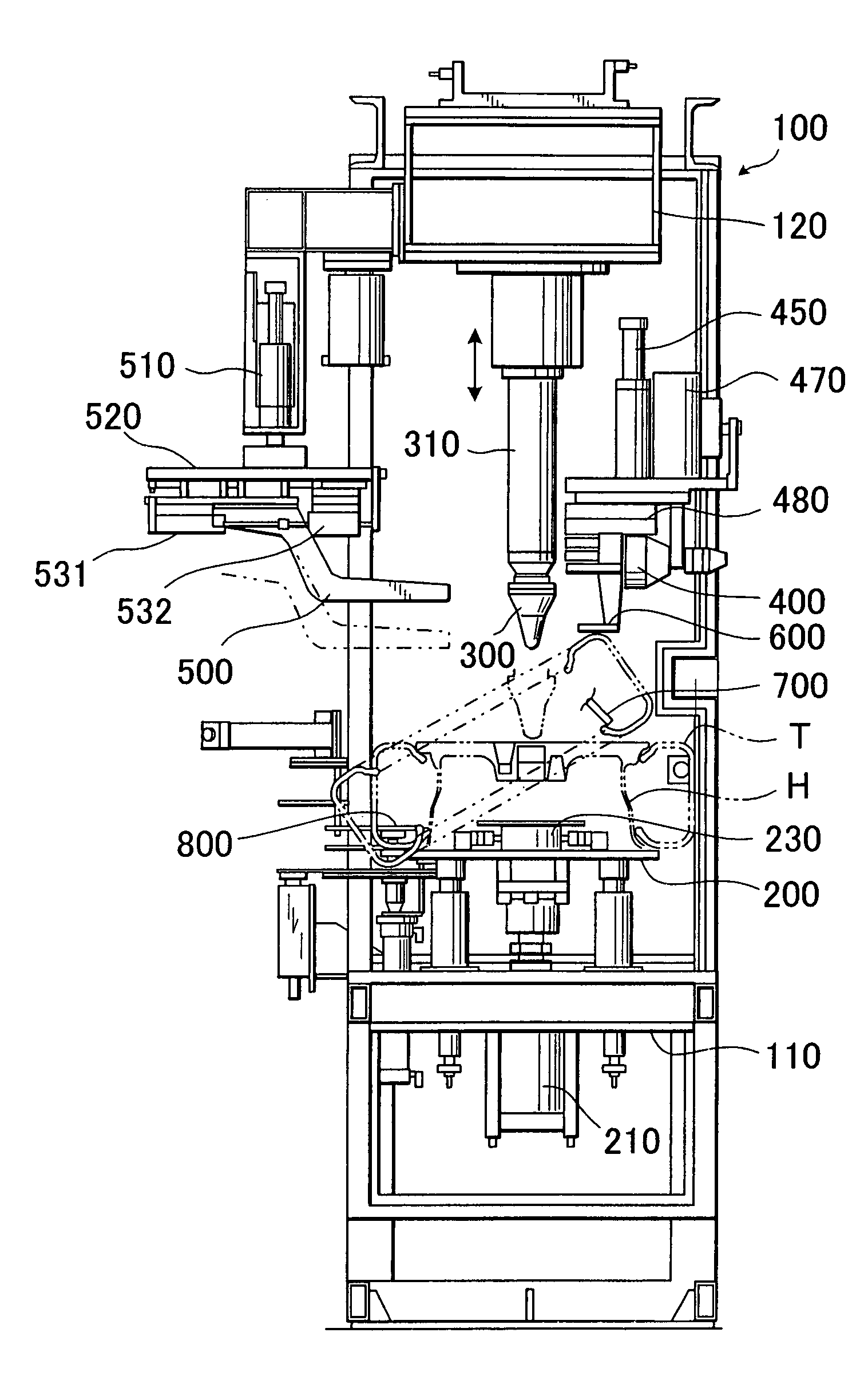
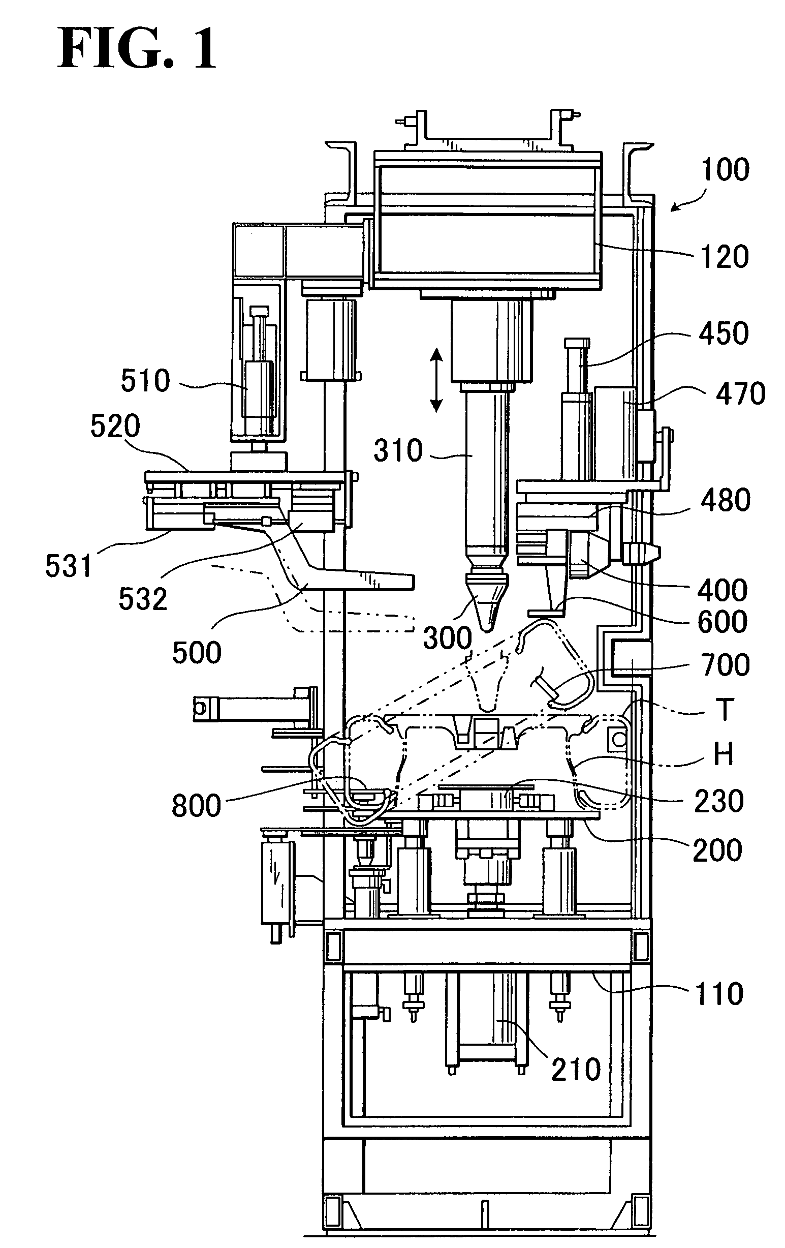
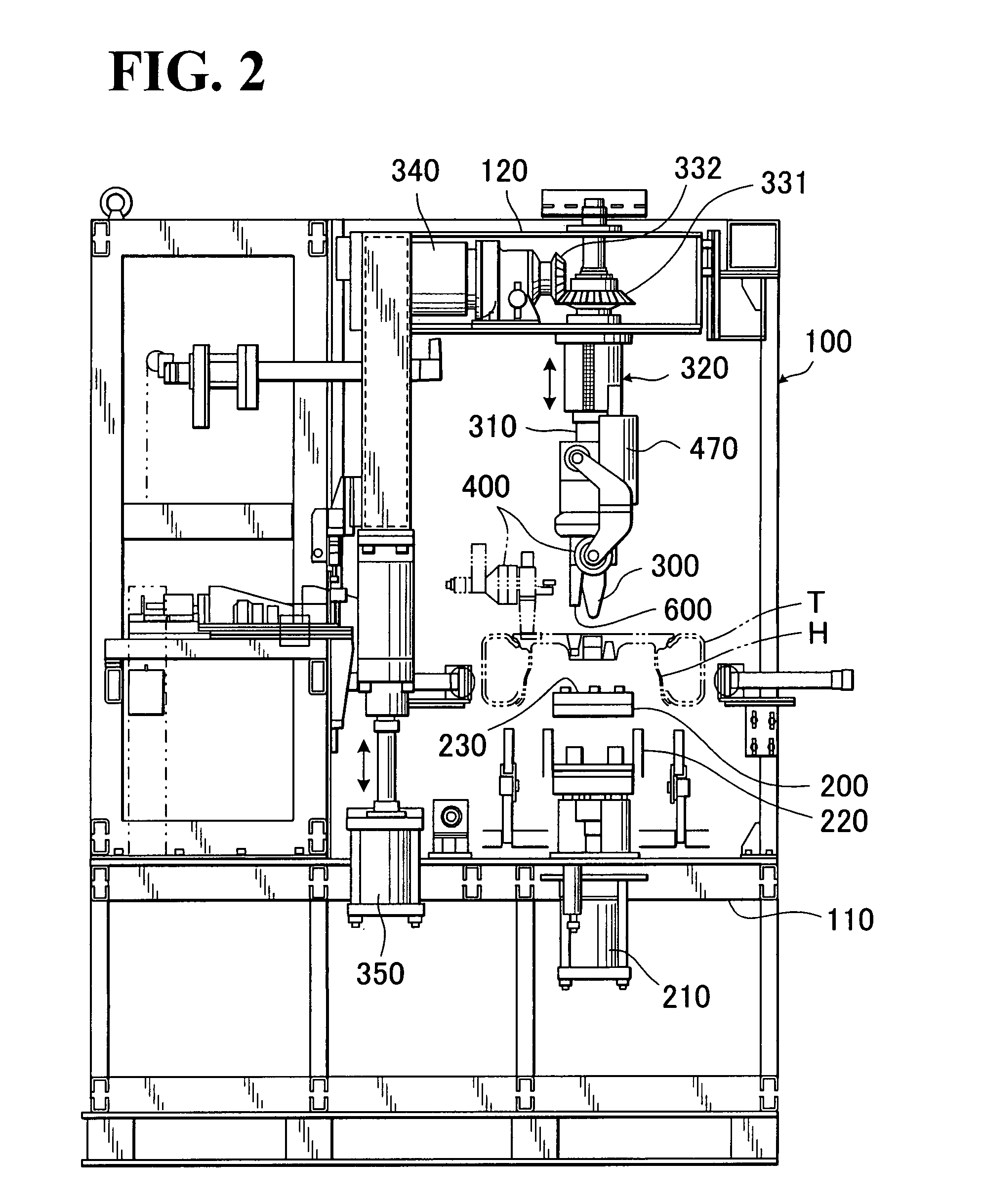
[0036]FIG. 1 and FIG. 2 are views showing the entire tire mounter of the invention.

[0037]In the same figures, depicted by 100 is a machine frame formed of a frame member such as a steel frame constituting a frame of a main body of the mounter, 200 is a lift table (wheel receiving table) on which a wheel H having a tire T which is temporarily fixed thereon aslant is placed, 300 is a center cone which is moved up and down relative to a wheel center hole of the wheel H placed on the lift table 200 and is rotatably mounted on a center cone shaft part 310, which will be described in detail later, 400 is a tire bead press roller which is pressed against an upper bead part side of the tire T, 500 is a tire presser which is pressed against the upper bead part side of the tire, 600 is a bead guide plate formed of an arc-shaped plate piece which is newly employed by the invention, and positioned and turned at the upper surface side of the wheel H when the tire T is mounted, and which function...


PUM


Abstract

The invention provides a tire mounter capable of preventing a tire from being damaged by minimizing a contact of a bead part of the tire relative to a wheel. The tire mounter, for receiving the wheel on which the tire is temporarily fixed aslant and mounting the tire on the wheel from a temporarily fixed state when mounting the tire, comprises a bead guide plate having an arc-shaped plate piece, the arc-shaped plate piece having a bottom surface side positioned on an upper surface side of the wheel, and an outer peripheral arc-shaped part positioned on an outer peripheral surface of the wheel. The bead guide plate is turned toward a bead part of the tire at a non-mounting side of the tire while being interlocked with a turning of a tire bead press roller, and thereby the bead guide plate turns ahead of the tire bead press roller so that the bead part of the tire at the non-mounting side of the tire slides on a surface side of the bead guide plate to be mounted on the wheel. With the configuration of this tire mounter, a contact load of the tire when mounting on the wheel can be significantly reduced, thereby minimizing the damage to the tire.

Description

FIELD OF THE INVENTION[0001]The invention relates to a tire mounter for preventing a tire from being damaged by significantly reducing friction of bead parts of the tire relative to a wheel when the tire is mounted on the wheel, and a method of mounting the tire on the wheel using the tire mounter.BACKGROUND OF THE INVENTION[0002]According to a conventional tire mounter for mounting a tire on a wheel, a tire bead press roller to be pressed against an upper bead part side of the tire and a tire presser to be pressed against the upper bead part side of the tire are used. The tire bead press roller is turned from a state where the tire is normally temporarily fitted on the wheel aslant, while the upper and the lower bead parts of the tire are compelled to contact the outer periphery (edge part) of the wheel to be slid by two motions (two times mounting operation) or one motion (one time mounting operation), thereby mounting the tire on a predetermined position of the wheel. Such a conv...

Claims


Application Information

Patent Timeline
Patent Type & Authority Patents(United States)
IPC IPC(8): B60C25/138
CPCB60C25/138B60C25/0503B60C25/0512B60C25/0518B60C25/0545B60C25/12
Inventor NOMURA, TERUJI
Owner HONDA LOGISTICS
Why Eureka
Try Eureka