Connector

a technology of connecting rods and connectors, applied in the direction of connection contact parts, connection connection, fixed connections, etc., can solve the problems of increasing the size of one electric connector and the inability to adequately shield the connectors, and achieve the effect of compact siz

Inactive Publication Date: 2009-09-08
JAPAN AVIATION ELECTRONICS IND LTD
View PDF7 Cites 75 Cited by
  • Summary
  • Abstract
  • Description
  • Claims
  • Application Information

AI Technical Summary

Benefits of technology

[0017]The present invention has been made in view of these circumstances, and an object thereof is to provide a connector which is capable of sufficiently shielding two connectors for electrically connecting two circuit boards, and making the connectors compact in size.
[0023]As described above, according to the present invention, it is possible to sufficiently shield two connectors for connecting two circuit boards and attain the reduction of the sizes of the connectors.

Problems solved by technology

This increases the size of the one electric connector.
To reduce the size of the one connector, it is only required to remove the shield plates from the one connector, but this makes it impossible to sufficiently shield the connectors.

Method used


Image

  • Connector
  • Connector
  • Connector

Examples


Embodiment Construction

[0040]The present invention will now be described in detail with reference to the drawings showing a preferred embodiment thereof.

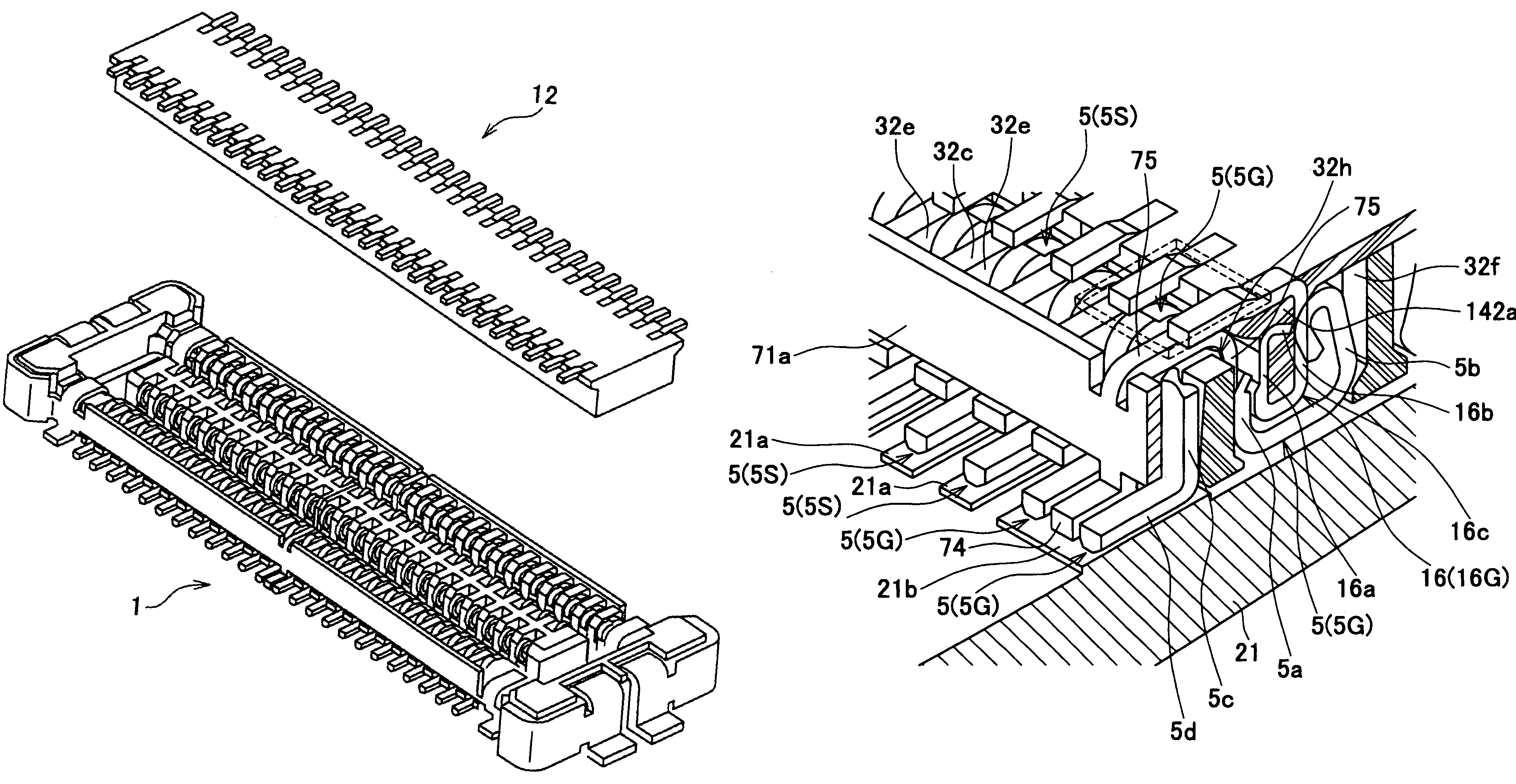
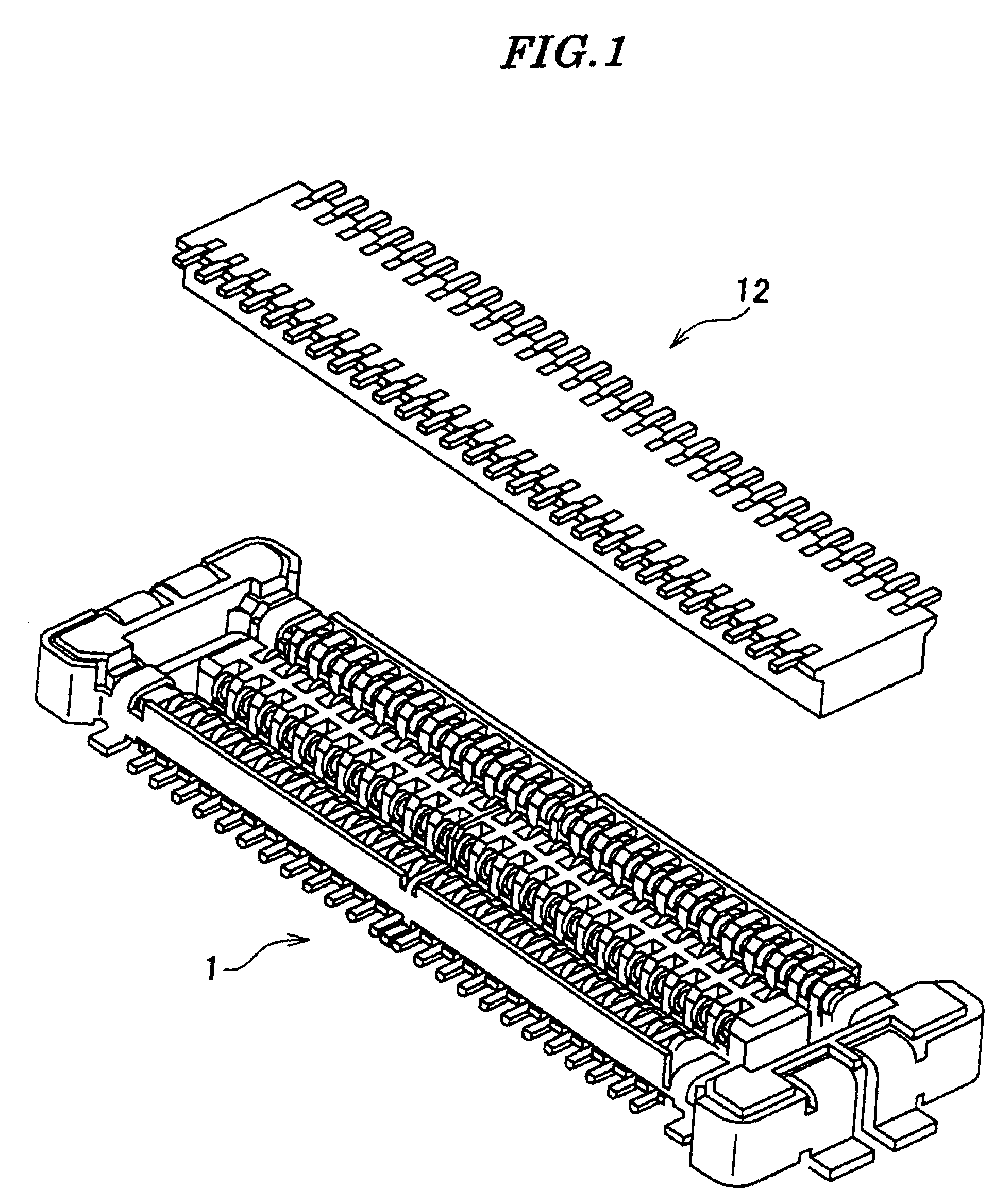
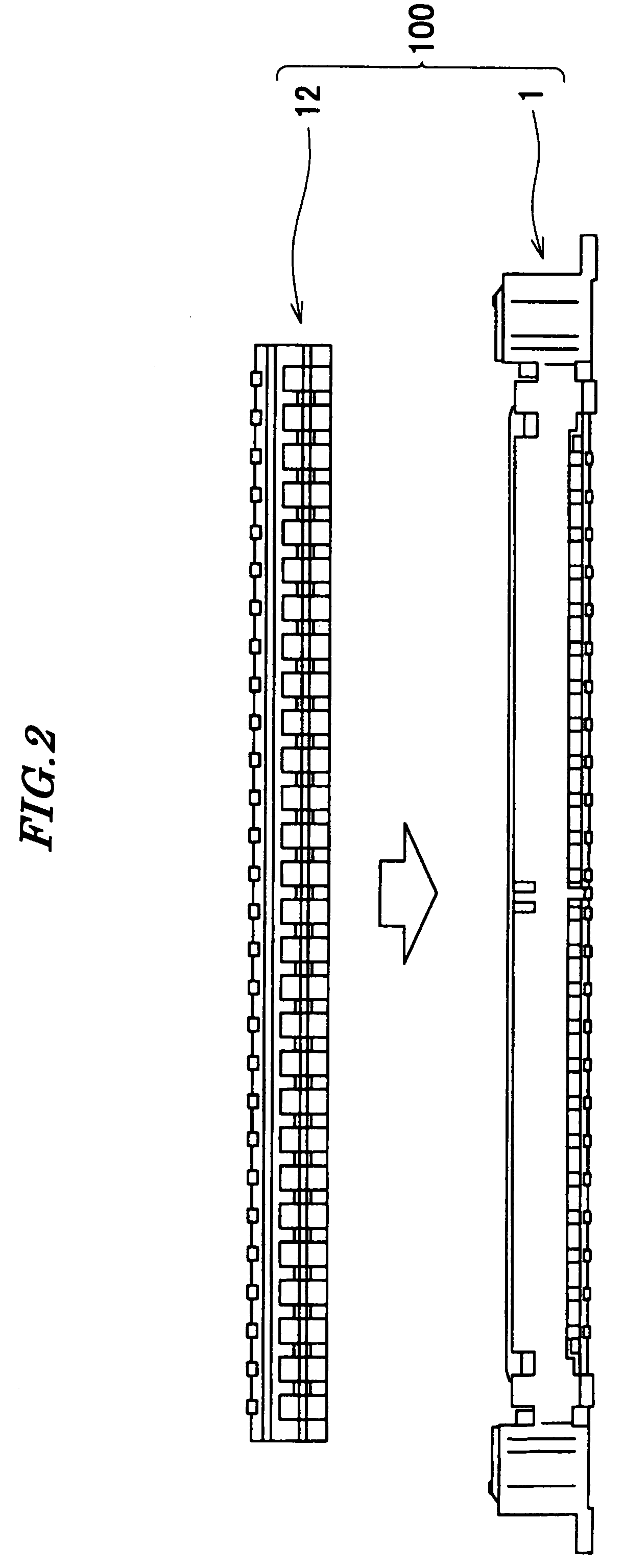
[0041]Referring to FIGS. 1 to 4, the connector device 100 is comprised of the receptacle connector (connector) 1 and a plug connector (mating connector) 12, The receptacle connector 1 is mounted on a first printed circuit board (circuit board) 21 (see FIG. 9) and the plug connector 12 is mounted on a second printed circuit board (mating circuit board), not shown.

[0042]As shown in FIG. 5, the receptacle connector 1 includes a receptacle-side housing (housing) 3, receptacle-side contacts (contacts) 5, and the shell 7.

[0043]As shown in FIGS. 6 to 8, the receptacle-side housing 3 includes a plate-like portion 31 and a receptacle-side fitting portion (fitting portion) 32.

[0044]The plate-like portion 31 is disposed on the first printed circuit board 21. The plate-like portion 31 is slightly lifted from the first printed circuit board 21.

[0045]The receptacle-sid...


PUM


Abstract

A connector capable of sufficiently shielding two connectors for connecting two circuit boards, and further making the connectors compact in size. A receptacle-side fitting portion (32) for being fitted to a plug-side fitting portion (142) of a plug connector (12) is formed in a receptacle-side housing (3) disposed on a printed circuit board (21). A plurality of receptacle-side contacts (5) are arranged in the receptacle-side fitting portion (32). A shell body (71) disposed around the receptacle-side fitting portion (32) is provided in a shell (7) mounted in receptacle-side housing (3). The shell (7) is formed with shell contact portions (72) brought into contact with plug-side ground contacts (16G) of the plug connector (12), and a shell terminal portion (73) fixed to a ground pad (21) of the printed circuit board (21).

Description

BACKGROUND OF THE INVENTION[0001]1. Field of the Invention[0002]This invention relates to a connector device for connecting two circuit boards, and more particularly to a connector device having shielding means.[0003]2. Description of the Related Art[0004]Conventionally, there has been proposed a connector formed by a pair of connectors fitted to each other (see Japanese Laid-Open Patent Publication (Kokai) No. H11-233201 (Paragraphs [0018], [0022], and [0028], and FIG. 8).[0005]One of the connectors is provided with a housing, a plurality of contacts, a plurality of shield plates, and a plurality of reinforcing end plates.[0006]The housing has a frame portion in the form of a frame, and a protrusion extending in the longitudinal direction of the frame portion and located in the center of the frame portion. A receiving space for receiving the fitting portion of a mating connector is formed between the frame portion and the protrusion. The protrusion has a plurality of holding groove...

Claims


Application Information

Patent Timeline
Patent Type & Authority Patents(United States)
IPC IPC(8): H01R13/648
CPCH01R13/65802H01R12/716H01R12/7082H01R12/714H01R12/52H01R12/57H01R13/6581H01R12/73H01R13/648
Inventor OBIKANE, HIROAKI
Owner JAPAN AVIATION ELECTRONICS IND LTD
Why Eureka
Try Eureka