
Throwing wheel assembly

a technology of throne wheel and assembly, which is applied in the direction of rotor blades, grinding/polishing apparatuses, manufacturing tools, etc., can solve the problems of tripping blade, wheel imbalance, and irregular performan

Inactive Publication Date: 2009-09-08
ROBERTS SINTO A MICHIGAN
View PDF7 Cites 14 Cited by
  • Summary
  • Abstract
  • Description
  • Claims
  • Application Information

AI Technical Summary

Benefits of technology

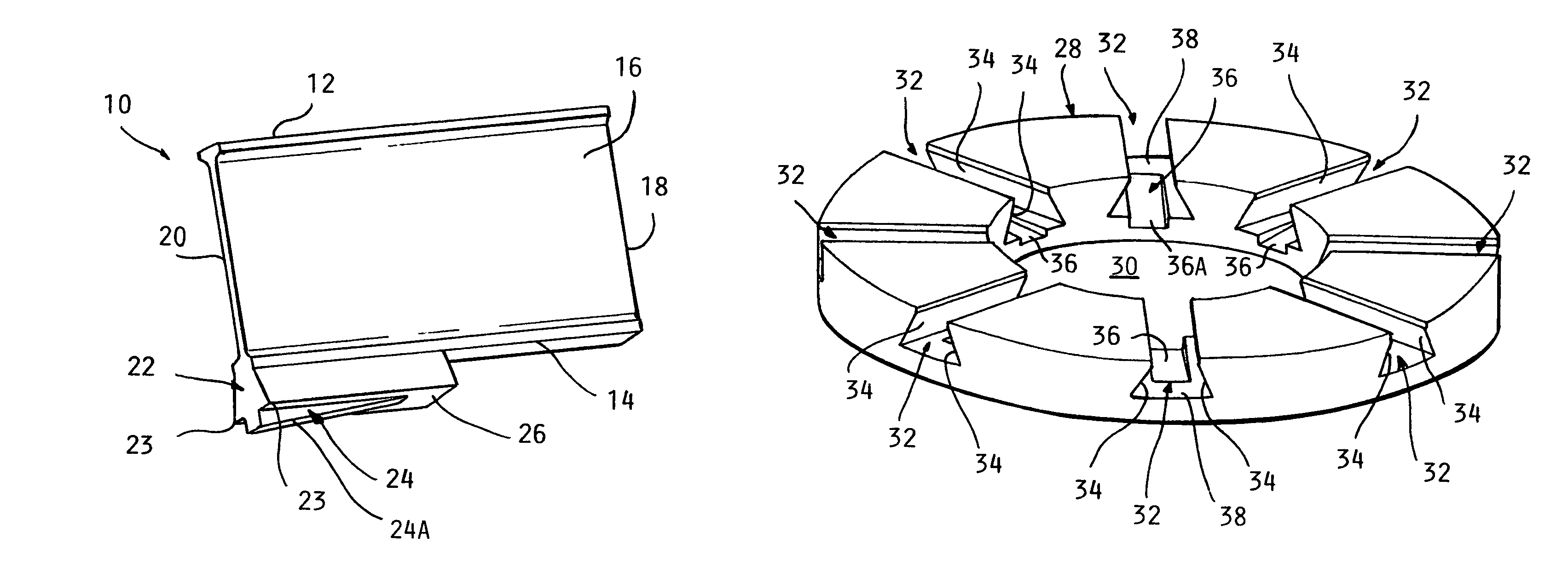
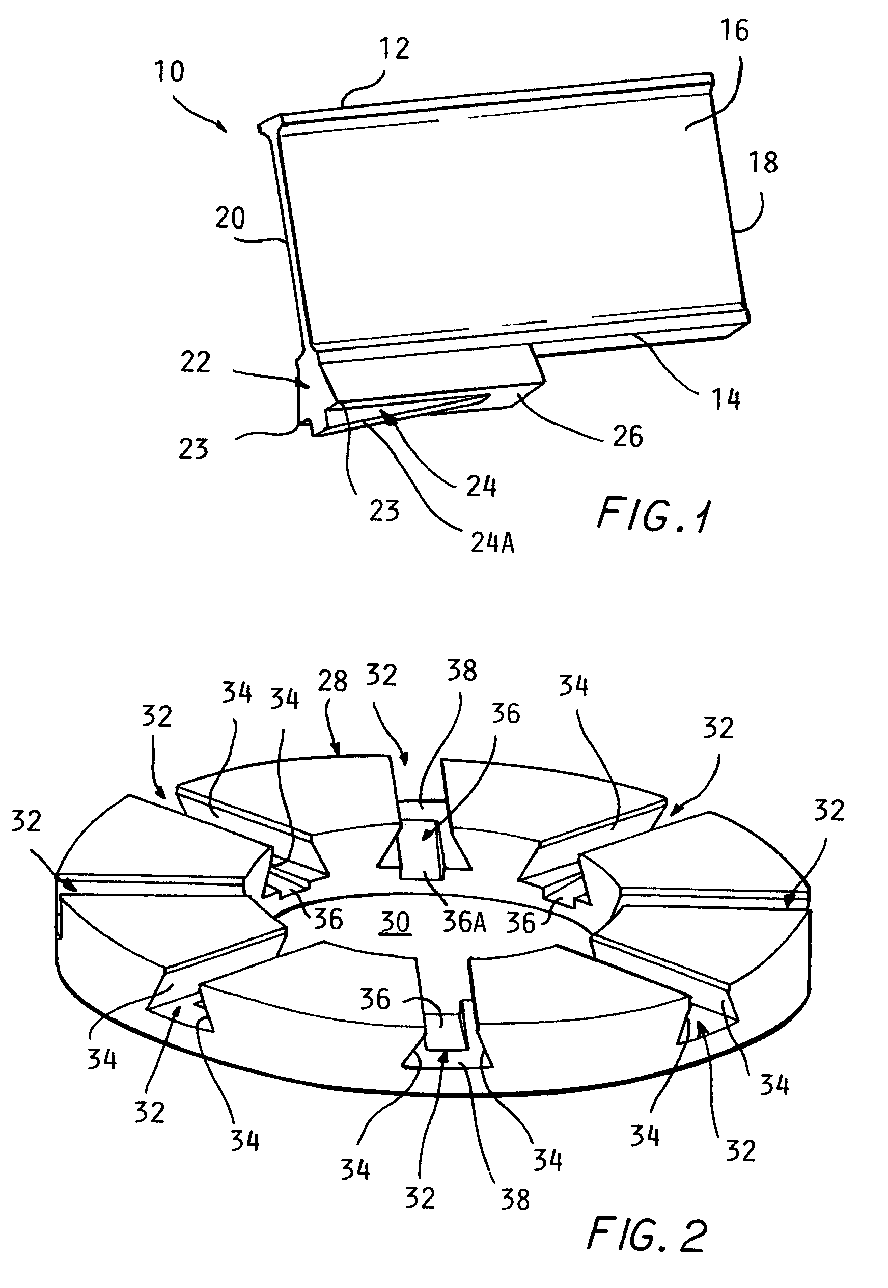
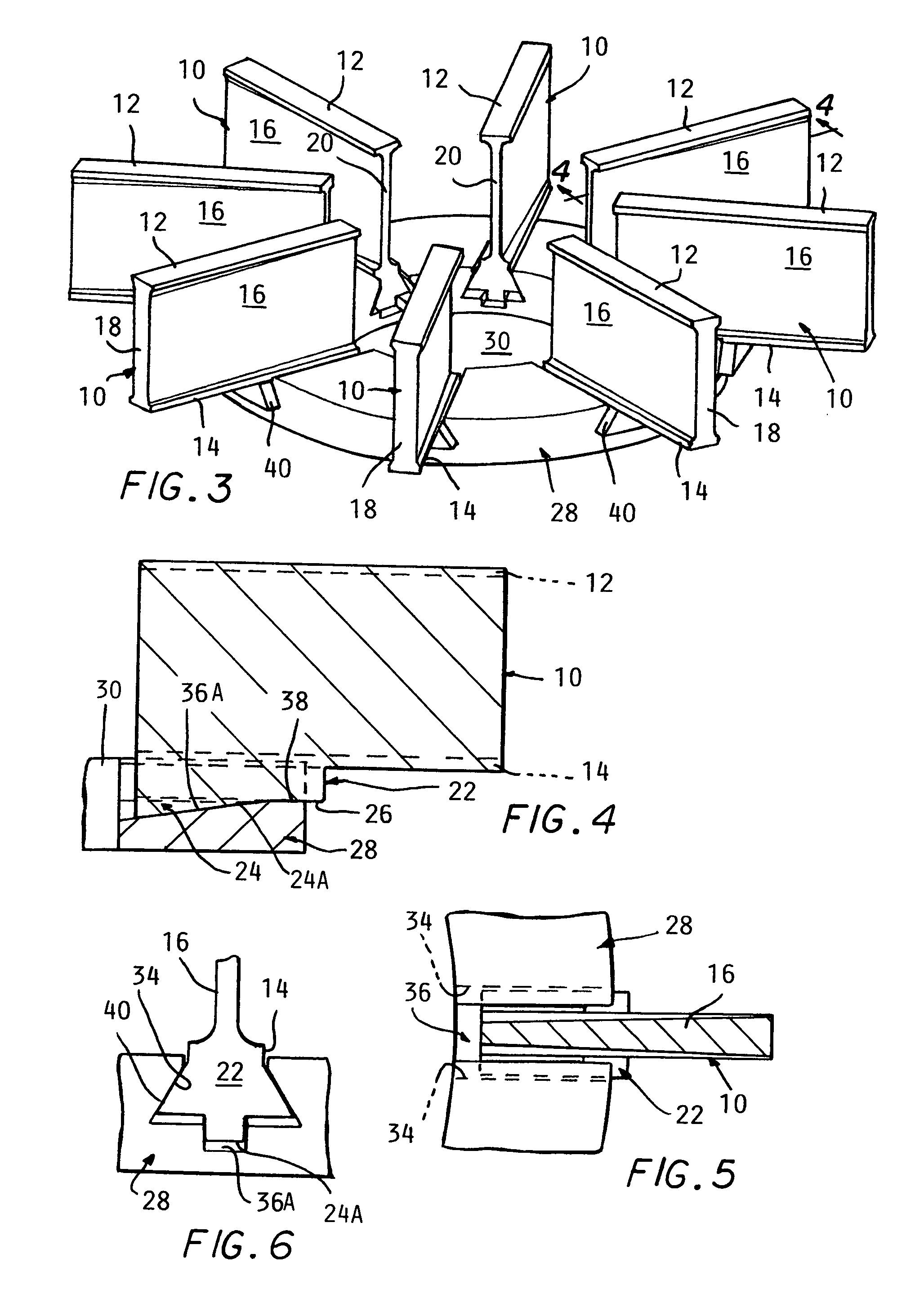
[0007]The above recited object and other objects which will be understood upon a reading of the following specification and claims are achieved by a throwing blade having a parallel dovetailed feature which is configured to engage sides of channels having dovetailed sides. In order to lock the blades in engagement with the dovetailed sides of a mating channels, a slot is formed into the bottom of each channel and a corresponding downwardly projecting cam ramp feature is formed on the base of each blade projecting below the dovetailed feature. The axially sloping bottom surface of the slot and the ramp top surface feature engage with each other to cam the dovetail base on the blade into tight engagement with the dovetailed channel sides to tightly lock the blade to the throwing wheel. With a simple ramp engagement, more accurate radial location of the blades can be achieved while using only conventional casting processes.

Problems solved by technology

The mounting must provide for accurate location on the wheel radially since varying of the radial position can result in a wheel imbalance when rotated at high speed.
Excessive clearance can result in tipping of the blade and irregular performance.
The mounting must provide for accurate location on the wheel radially since varying of the radial position can result in a wheel imbalance when rotated at high speed.
Excessive clearance is a result in tipping of the blade and irregular performance.
In addition, any clearance spaces can result in abrasive material entering those spaces and make it difficult or impossible to remove the blade for replacement.
However, the tapered dovetail is difficult to form accurately by normal casting processes and accuracy of the radial location of the blade may suffer if there are inaccuracies in forming the double tapered dovetail shape.
These radial location variations are problematic as described above.
This requires separate spring elements which can get broken and lost.

Method used


Image

  • Throwing wheel assembly
  • Throwing wheel assembly
  • Throwing wheel assembly

Examples


Embodiment Construction

[0014]In the following detailed description, certain specific terminology will be employed for the sake of clarity and a particular embodiment described in accordance with the requirements of 35 USC 112, but it is to be understood that the same is not intended to be limiting and should not be so construed inasmuch as the invention is capable of taking many forms and variations within the scope of the appended claims.

[0015]Referring to the drawings and particularly FIGS. 1 and 2, a throwing blade 10 according to the invention is shown adapted to be mounted to a throwing wheel 28 rotated about a central axis in the well known manner. The throwing blade 10 is comprised of a generally rectangular steel casting having an upper and lower edges formed with flanges 12, 14 and a web 16 defining the throwing surfaces. The web 16 is tapered as per conventional practice (as shown in FIG. 5), being thicker at a radially outer end 18 than at a radially inner end 20 of the blade 10.

[0016]According...


PUM


Abstract

A throwing wheel assembly including a wheel and a series of throwing blades mounted in radial channels in the wheel formed with mating dovetail wing portions on the slot sides and a projecting at the base of the blade. A sloping grove in the bottom of each channel engages a projecting ramp feature on the base of the mating blade received therein to cam the blade outwardly and thereby create a tight fit of the dovetail portions and to lock the blades in position.

Description

BACKGROUND OF THE INVENTION[0001]The throwing blades must be removable since they wear out and must be routinely replaced. The mounting must provide for accurate location on the wheel radially since varying of the radial position can result in a wheel imbalance when rotated at high speed. Excessive clearance can result in tipping of the blade and irregular performance.[0002]The throwing blades must be removable since they wear out and must be routinely replaced. The mounting must provide for accurate location on the wheel radially since varying of the radial position can result in a wheel imbalance when rotated at high speed. Excessive clearance is a result in tipping of the blade and irregular performance.[0003]In addition, any clearance spaces can result in abrasive material entering those spaces and make it difficult or impossible to remove the blade for replacement.[0004]U.S. Pat. No. 5,476,412 describes a method using a tapered dovetail channel to create a tight fit which wedge...

Claims


Application Information

Patent Timeline
Patent Type & Authority Patents(United States)
IPC IPC(8): B24C5/06
CPCB24C5/062
Inventor BARRIGER, ALLAN
Owner ROBERTS SINTO A MICHIGAN
Learn More