Multiple component wall plate

a wall plate and multi-component technology, applied in the direction of electrical apparatus casings/cabinets/drawers, coupling device connections, casings/cabinets/drawers, etc., can solve the problems of reducing the aesthetics of the plate, so as to achieve easy replacement and/or interchangeability, the effect of less capital investmen

Inactive Publication Date: 2009-09-08
PASS SEYMOUR
View PDF30 Cites 18 Cited by
  • Summary
  • Abstract
  • Description
  • Claims
  • Application Information

AI Technical Summary

Benefits of technology

[0006]The present invention addresses the needs described above. The present invention provides a cover plate customized to match the décor, furniture or appliances in a room. The present invention is advantageously directed to a cover plate assembly that includes components that are easily replaceable and / or interchangeable, allowing the homeowner to purchase new decorative components to match a new décor, without having to replace the entire decorative wall plate assembly. This feature is also advantageous to the manufacturer because it allows the manufacturer to provide a certain “mix-and-matchability” and / or customizability for less capital investment.

Problems solved by technology

There are several drawbacks to conventional wall plates.
Conventional wall plates are relatively unattractive and generally have little decorative appeal.
The attachment screws are visible, which further detracts from any aesthetic qualities that the plate may have.

Method used


Image

  • Multiple component wall plate
  • Multiple component wall plate
  • Multiple component wall plate

Examples


Embodiment Construction

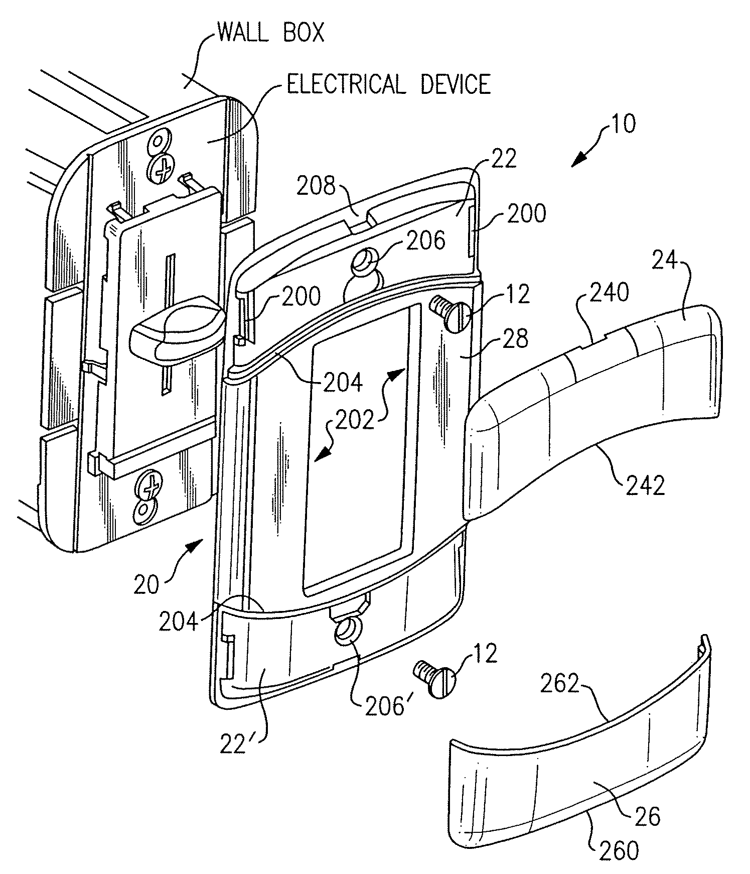
[0026]Reference will now be made in detail to the present exemplary embodiments of the invention, examples of which are illustrated in the accompanying drawings. Wherever possible, the same reference numbers will be used throughout the drawings to refer to the same or like parts. An exemplary embodiment of the decorative wall plate assembly of the present invention is shown in FIG. 1, and is designated generally throughout by reference numeral 10.

[0027]As embodied herein, and depicted in FIG. 1, an exploded view of a decorative wall plate assembly 10 in accordance with an embodiment of the present invention is disclosed. Assembly 10 includes base plate 20 and cover caps 24, 26. Base plate 20 is configured to be mounted to the electrical device by fasteners 12. The fasteners 12 are inserted into screw holes 206 and mate with corresponding screw holes formed in the electrical device, wall box, or structural member. Alternatively, fasteners 12 include snaps (not shown) that are rearwar...


PUM


Abstract

The present invention is directed to a decorative wall plate assembly configured to cover at least one electrical device disposed in a wall box. The assembly includes a base plate member comprising a center portion including at least one aperture configured to accommodate the at least one electrical device, a first end portion of the base plate member including at least one first plate connection device, and a second end portion of the base plate member including at least one second plate connection device. The center portion is disposed between the first end portion and the second end portion. A first cover cap includes at least one first cover cap connection device configured to mate with the at least one first plate connection device. The first cover cap is configured to cover the first end portion. A second cover cap includes at least one second cover cap connection device configured to mate with the at least one second plate connection device. The second cover cap is configured to cover the second end portion.

Description

BACKGROUND OF THE INVENTION[0001]1. Field of the Invention[0002]The present invention relates generally to wall plate systems, and particularly to customized wall plates.[0003]2. Technical Background[0004]Electrical wiring devices such as switches, GFCIs, AFCIs, electrical outlets, dimmers, night-lights, TVSSs, surge protective device (SPD), proximity sensing devices and the like are installed in wall boxes attached to a structural member and covered by a wall plate. Structural members include counter-top surfaces, panels, walls, floors, ceilings, and the like. Conventional wall plates typically have a rectangular form factor and may be formed from plastic, metal or wood materials. Conventional plates include screw holes, disposed at the top and bottom of the wall plate, as a means for fastening the plate to the wiring device, wall box, or structural member. There are several drawbacks to conventional wall plates. Conventional wall plates are relatively unattractive and generally ha...

Claims


Application Information

Patent Timeline
Patent Type & Authority Patents(United States)
IPC IPC(8): H02G3/14
CPCH02G3/14
Inventor BALA, KAPIL RAO GANTA PAPA RAOJUNKO, THEODORE P.
Owner PASS SEYMOUR
Why Eureka
Try Eureka