ID tag
a technology of id tags and tags, applied in the field of id tags, can solve the problems of inability to enjoy the convenient function of id tags, inability to safely protect personal information, and disassembly and maintenance of id tags,
- Summary
- Abstract
- Description
- Claims
- Application Information
AI Technical Summary
Benefits of technology
Problems solved by technology
Method used
Image
Examples
first embodiment
[0061]First, a general configuration of an ID tag having a time switch according to the present invention will be explained.
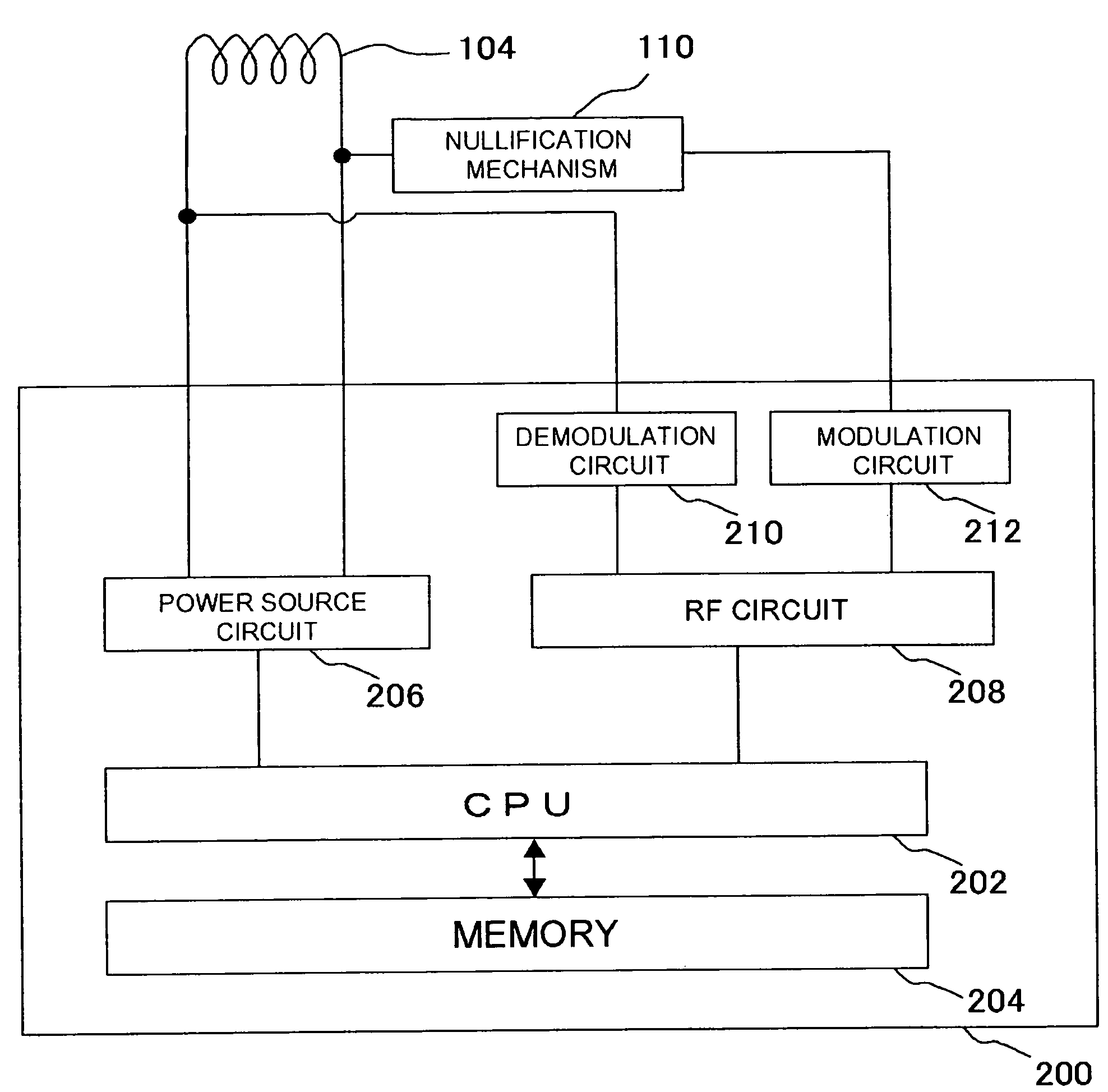
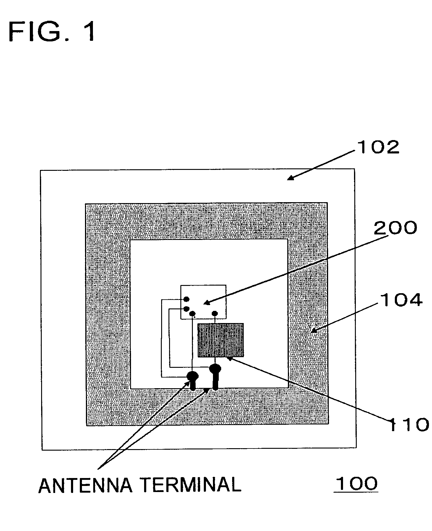
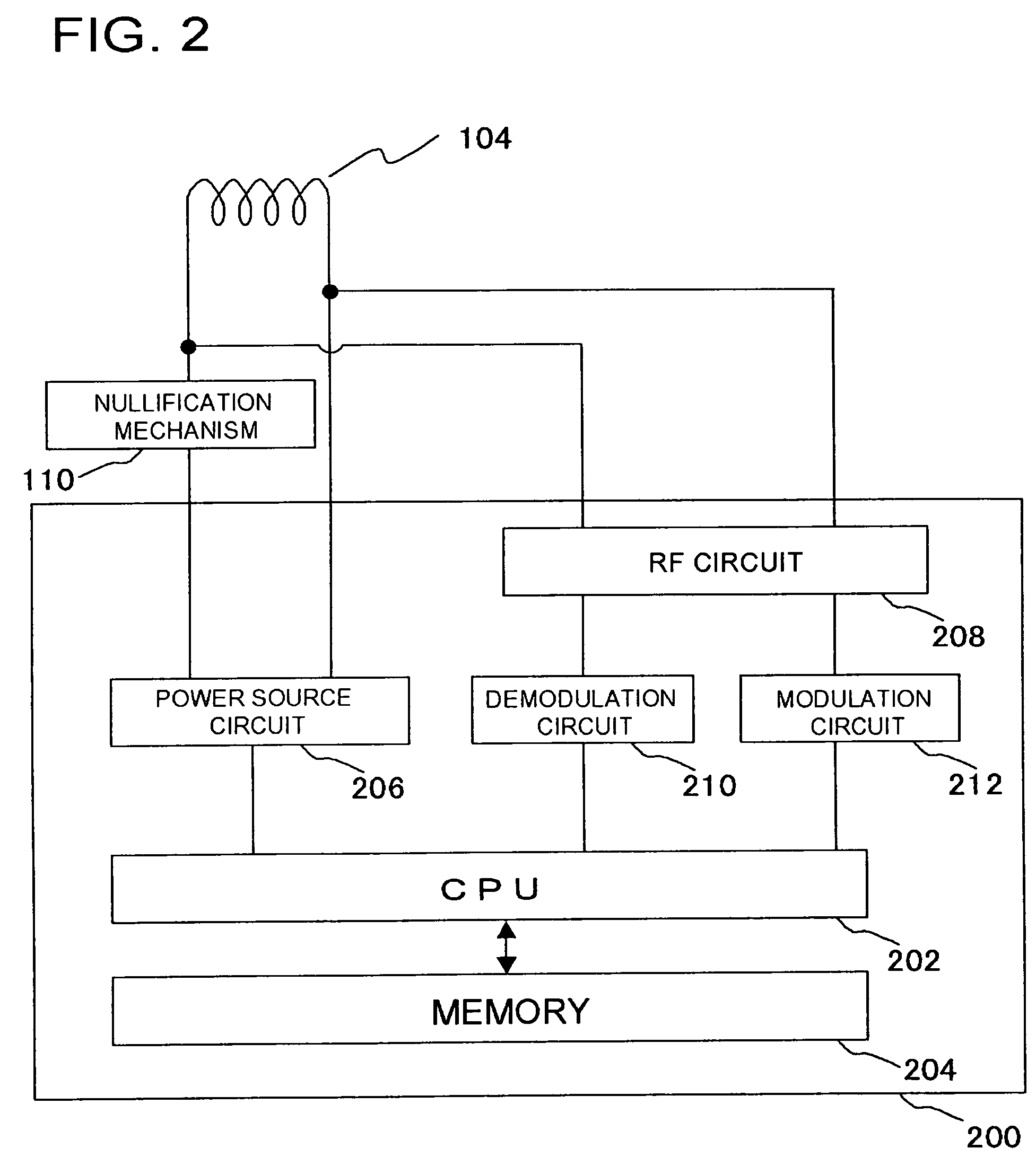
[0062]FIG. 1 is a drawing showing an internal structure of an exemplary RFID tag of this embodiment. The RFID tag 100 has a circuit including an antenna (coil antenna 104) and an IC chip 200, and a nullification unit (nullification mechanism 110) isolating the circuit. The nullification unit (nullification mechanism 110) includes a time switch isolating the circuit when a predetermined time limit for operation has reached after the start of use of the ID tag. A coil antenna 104, an IC chip 200 and a nullification mechanism 110 are provided on a substrate 102.
[0063]The IC chip 200 is a thin chip having a communication circuit which takes part in transmission of various data to or from an external reader / writer, and a memory storing various data incorporated therein. The coil antenna 104 applicable herein may be such as being formed by pattern-forming printing wi...
second embodiment
[0072]In this embodiment, an exemplary time switch included in the nullification mechanism 110 will be explained.
(General Structure)
[0073]FIG. 4 is a drawing showing a general configuration of a solid electrolyte switch 300 as an example of the time switch according to the present invention. The switch makes use of a phenomenon such that a conduction channel formed in the solid electrolyte film in the initial state thereof disappears with time.
[0074]FIG. 4(a) is a drawing schematically showing a state of the solid electrolyte switch 300 in the switched-off state. As shown in the drawing, the solid electrolyte switch 300 has a pair of electrodes 302 opposed with each other, and a solid electrolyte 308 held therebetween. An ion supplying layer 304 is provided on the inner surface of one of the electrodes 302. Metal ions 306 released from the ion supplying layer 304 reside in the solid electrolyte 308 in a distributed manner. In an equilibrium state, there is no electro-conductivity be...
third embodiment
[0107]This embodiment shows an example of a narrow metal line composed of a metal or a semiconductor, which can be converted into an insulating material through oxidation, applied to the time nullification switch. FIG. 10 is a schematic drawing of the RFID tag of this embodiment.
[0108]The RFID tag 100 has the circuit including the antenna (coil antenna 104) and the IC chip 200, and the nullification unit (time switch 112) isolating the circuit. The nullification unit (time switch 112) isolates the circuit when a predetermined time limit for operation has reached after the start of use of the ID tag. The coil antenna 104, the IC chip 200 and the nullification mechanism 110 are provided on the substrate 102.
[0109]The IC chip 200 is a thin chip having a communication circuit which takes part in transmission of various data to or from an external reader / writer, and a memory storing various data incorporated therein. The coil antenna 104 applicable herein may be such as being formed by p...
PUM
 Abstract
Description
Claims
Application Information
 - R&D
- Intellectual Property
- Life Sciences
- Materials
- Tech Scout
- Unparalleled Data Quality
- Higher Quality Content
- 60% Fewer Hallucinations
Browse by: Latest US Patents, China's latest patents, Technical Efficacy Thesaurus, Application Domain, Technology Topic, Popular Technical Reports.
© 2025 PatSnap. All rights reserved.Legal|Privacy policy|Modern Slavery Act Transparency Statement|Sitemap|About US| Contact US: help@patsnap.com


