

Crimping device
a crimping device and crimping technology, applied in the direction of shaping safety devices, manufacturing tools, presses, etc., can solve the problems of measuring the crimping force of the entire device, the sensor is built into the wear part, etc., and achieve the effect of precise measurement of the crimping for
- Summary
- Abstract
- Description
- Claims
- Application Information
AI Technical Summary
Benefits of technology
Problems solved by technology
Method used
Image

Examples
Embodiment Construction
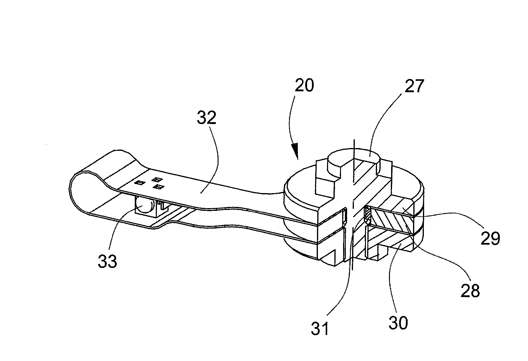
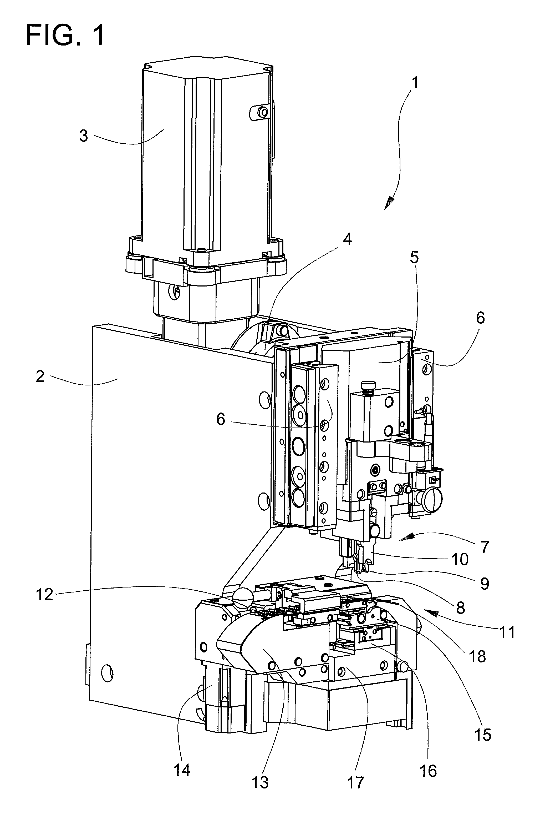
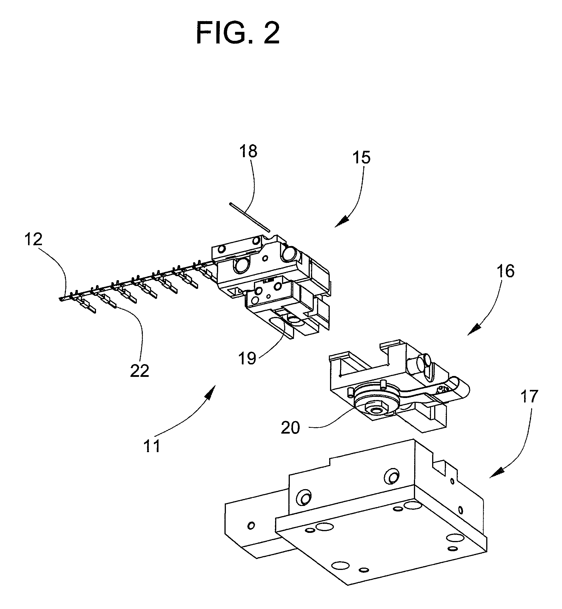
[0015]FIG. 1 shows a crimping press 1 according to the present invention comprising a first housing 2 on which a press motor 3 that drives a gear 4 is arranged. Provided on the output side of the gear is an eccentric device that converts the rotational motion of the motor 3 and gear 4 into a linear up-and-down motion that can be transferred to a press carriage 5, the press carriage 5 being guided by means of guides 6. Provided for the production of a crimped fastening between a crimp contact 22 (FIG. 2) and wire 18, and arranged on the press carriage 5, is an upper tool 7 with conductor crimper 8, an insulation crimper 9, and a cutter plunger 10, the upper tool 7 working in conjunction with a lower tool 11. The lower tool 11 comprises an anvil part 15, a sensor part 16, and a first supporting part 17. The crimp contacts 22 to be processed are parts of a contact belt 12 that is advanced by a contact advancer 13. An advancing motor 14 drives the contact advancer 13.
[0016]FIG. 2 shows ...
PUM
| Property | Measurement | Unit |
|---|---|---|
| crimping force | aaaaa | aaaaa |
| piezoelectric | aaaaa | aaaaa |
| shape | aaaaa | aaaaa |
Abstract
Description
Claims
Application Information