Roller mount for a roller of a conveyer

Active Publication Date: 2009-09-15
WORLDWIDE LOGISTICS CORP
View PDF7 Cites 12 Cited by
  • Summary
  • Abstract
  • Description
  • Claims
  • Application Information

AI Technical Summary

Benefits of technology

[0009]The main objective of the invention is to provide a roller mount for a roller of a con

Problems solved by technology

Additionally, two fasteners are needed for the conventional roller mount, so

Method used


Image

  • Roller mount for a roller of a conveyer
  • Roller mount for a roller of a conveyer
  • Roller mount for a roller of a conveyer

Examples


Embodiment Construction

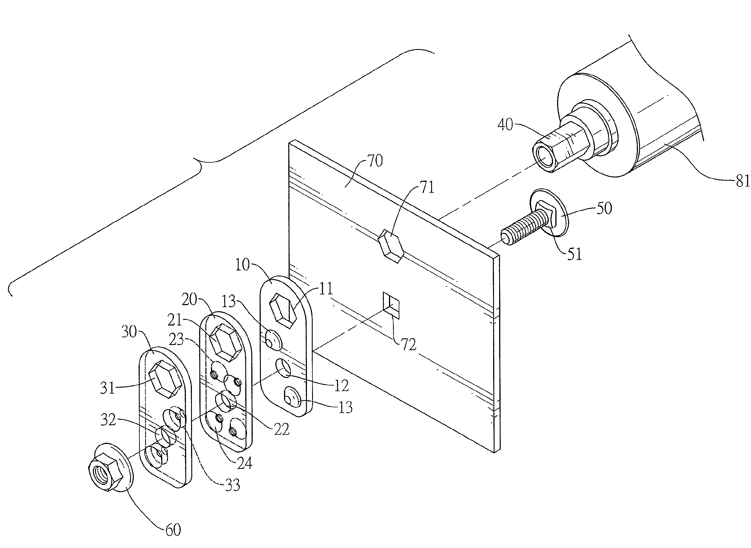
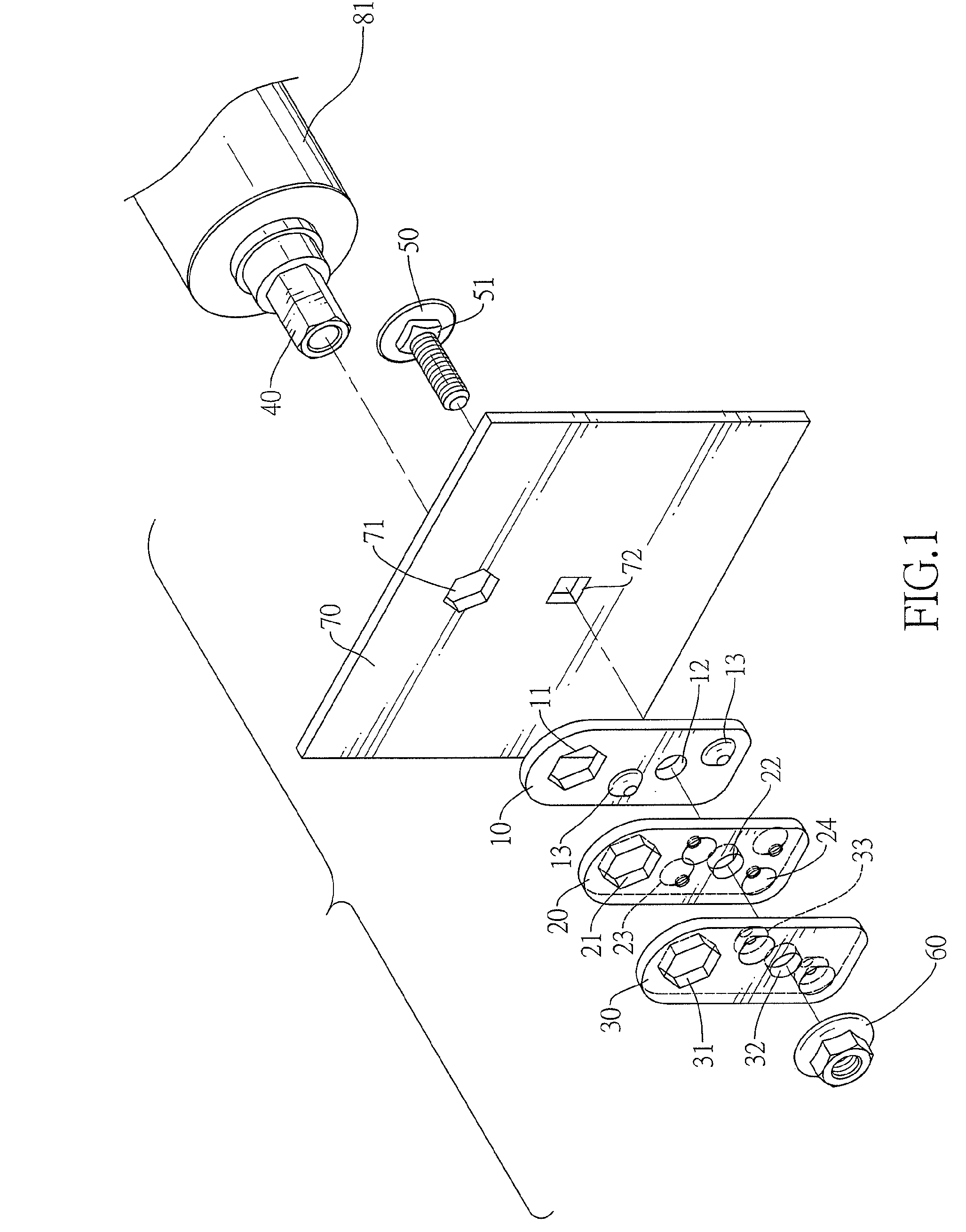
[0019]With reference to FIGS. 1 to 4, a roller mount for a roller (81) of a conveyer in accordance with the present invention comprises an axle (40), multiple holding panels (10,20,30) and a fastener.

[0020]The axle (40) is rotatably connected with the roller (81) and has a connecting end with a polygonal cross section.

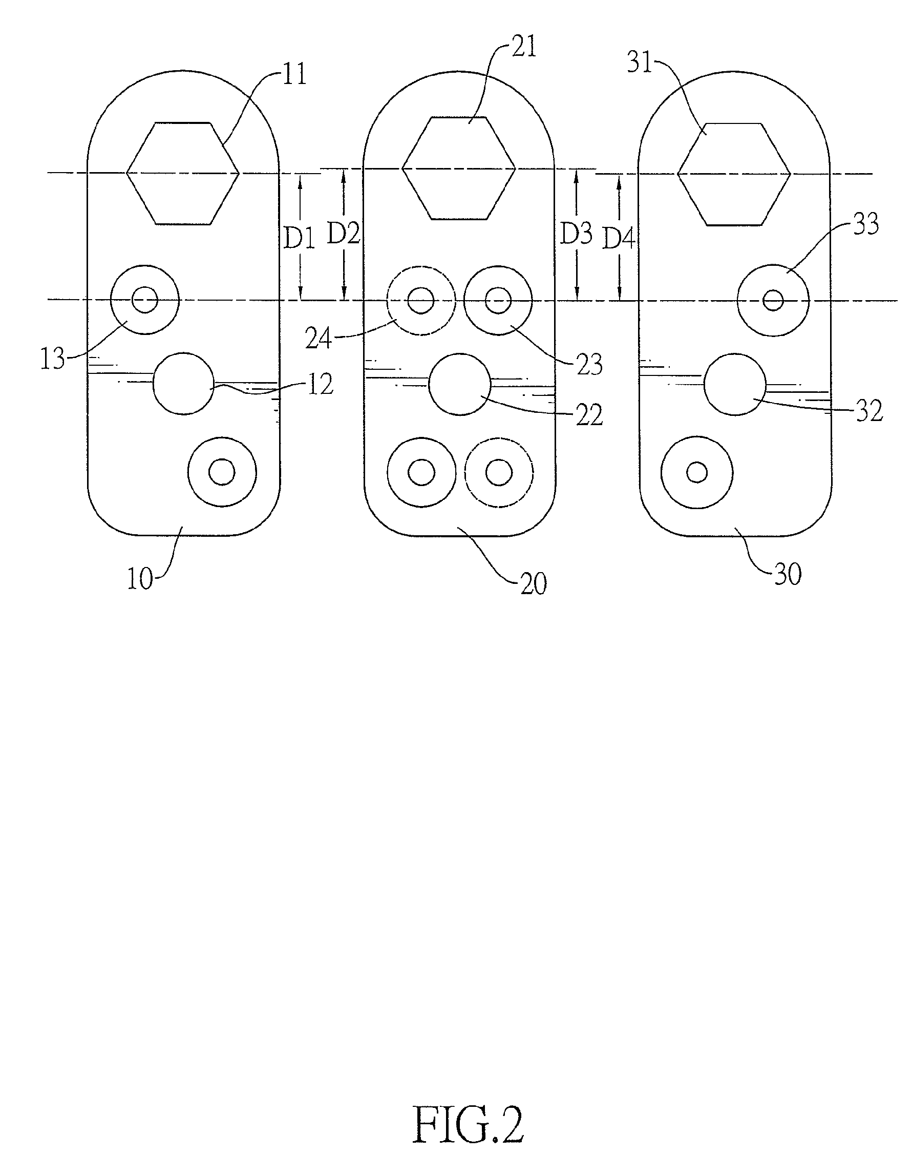
[0021]The holding panels (10,20,30) are mounted around the connecting end of the axle (40) to securely support the connecting end of the axle (40) and connect the axle (40) to a base (70) of the conveyer. In a preferred embodiment, the roller mount has three holding panels (10,20,30) including a first holding panel (10), a second holding panel (20) and a third holding panel (30). The second holding panel (20) is mounted and squeezed between the first and third holding panels (10,30).

[0022]Each holding panel (10,20,30) has a positioning hole (11,21,31) and a securing hole (12,22,32). The positioning hole (11,21,31) is defined through the holding panel (10,20,30), is pol...


PUM


Abstract

A roller mount for a roller of a conveyer has an axle, multiple holding panels, and a fastener. The holding panels are mounted around a connecting end of the axle, and each has a positioning hole and a securing hole. The positioning hole has a diameter larger than that of the connecting end of the axle. At least one pair of male-female combination is defined between each pair of adjacent holding panels. A distance between an uppermost one pair of the at least one male-female combination and the positioning hole in one of a corresponding pair of adjacent holding panels is different that between the uppermost pair of male-female combination and the positioning hole in the other of the pair of adjacent holding panels. The fastener is mounted through the aligning securing holes in the holding panels.

Description

BACKGROUND OF THE INVENTION[0001]1. Field of the Invention[0002]The present invention relates to a roller mount, and more particularly to a roller mount for a roller of a conveyer.[0003]2. Description of Related Art[0004]With reference to FIG. 5, a conveyer substantially comprises a base (80) and multiple rollers (81) rotatably mounted on the base to deliver objects, wherein some of the rollers (81) are powered. To rotatably mount the rollers (81) on the base (80), multiple roller mounts are mounted on the base (80). With further reference to FIGS. 6 and 7, a conventional roller mount comprises an axle (82), a securing board (90), two positioning panels (91,92) and two fasteners. The axle (82) is rotatably connected with a roller (81) and has a connecting end with a hexagonal cross section. The securing board (90) is securely mounted on the base (80) and has a hexagonal positioning hole (901) mounted around the connecting end of the axle (82). Two convex protrusions (902) formed on ...

Claims


Application Information

Patent Timeline
IPC IPC(8): B65G13/00
CPCB65G39/12
Inventor CHUANG, WILLIAM
Owner WORLDWIDE LOGISTICS CORP
Why Eureka
Try Eureka