Reduction gear and vehicular active stabilizer system

a technology of reduction gear and stabilizer, which is applied in the direction of gearing details, gearing, transportation and packaging, etc., can solve the problems of increasing the number of components and cost, increasing the cost of actuators, and increasing the cost, so as to facilitate the change of the reduction ratio and reduce the number of components

Inactive Publication Date: 2009-09-15
HONDA MOTOR CO LTD
View PDF5 Cites 8 Cited by
  • Summary
  • Abstract
  • Description
  • Claims
  • Application Information

AI Technical Summary

Benefits of technology

[0007]The present invention has been made in view of the above situation, and has an object to provide a small reduction gear which provides a large reduction ratio and facilitates a change of the reduction ratio.
[0009]With the first aspect of the present invention, the reduction gear includes: the rotatable carrier; the ring gear rotatably fitted in the offset supporting hole in the carrier; and the first and second sun gears having the first and second outer teeth meshed with the inner teeth of the ring gear, respectively. The rotation of the carrier is reduced in speed and outputted as relative rotation of the first and second sun gears. Thus, it is possible to secure a large reduction ratio although in a small structure having a small number of components. Also, it is possible to change the reduction ratio by a slight design change, e.g., changing the number of teeth in one of the outer teeth of the first and second sun gears, thereby improving the versatility.
[0011]With the second aspect of the present invention, the bearing interposed between the carrier and the ring gear enables a smooth relative rotation therebetween.

Problems solved by technology

Because the above conventional stabilizer is a type using a planetary gear mechanism as a reduction gear of an actuator, three planetary gear mechanisms are required to obtain a sufficient reduction ratio, leading to a problem that the number of components and cost are increased and the actuator becomes large.
Also, in order to change the reduction ratio of the reduction gear of the actuator, a design change of the entire planetary gear mechanisms is required, leading to a problem of a further increased cost.

Method used


Image

  • Reduction gear and vehicular active stabilizer system
  • Reduction gear and vehicular active stabilizer system
  • Reduction gear and vehicular active stabilizer system

Examples


Embodiment Construction

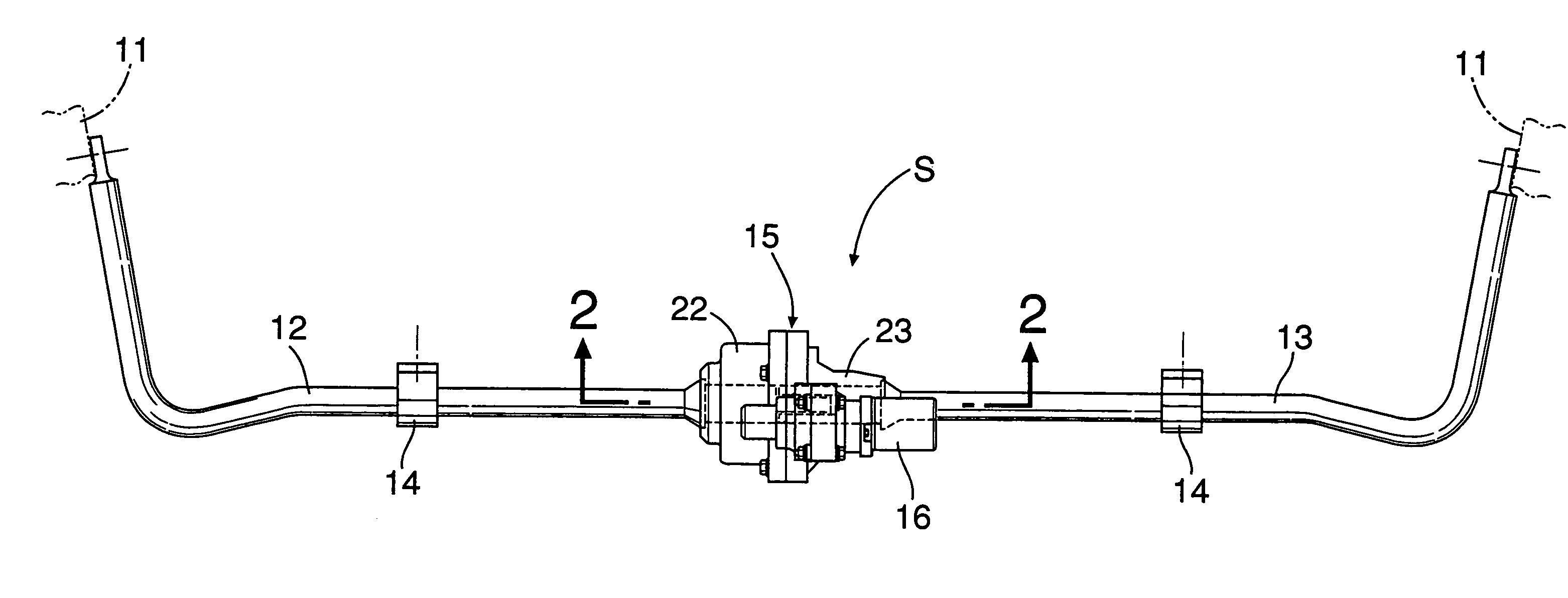
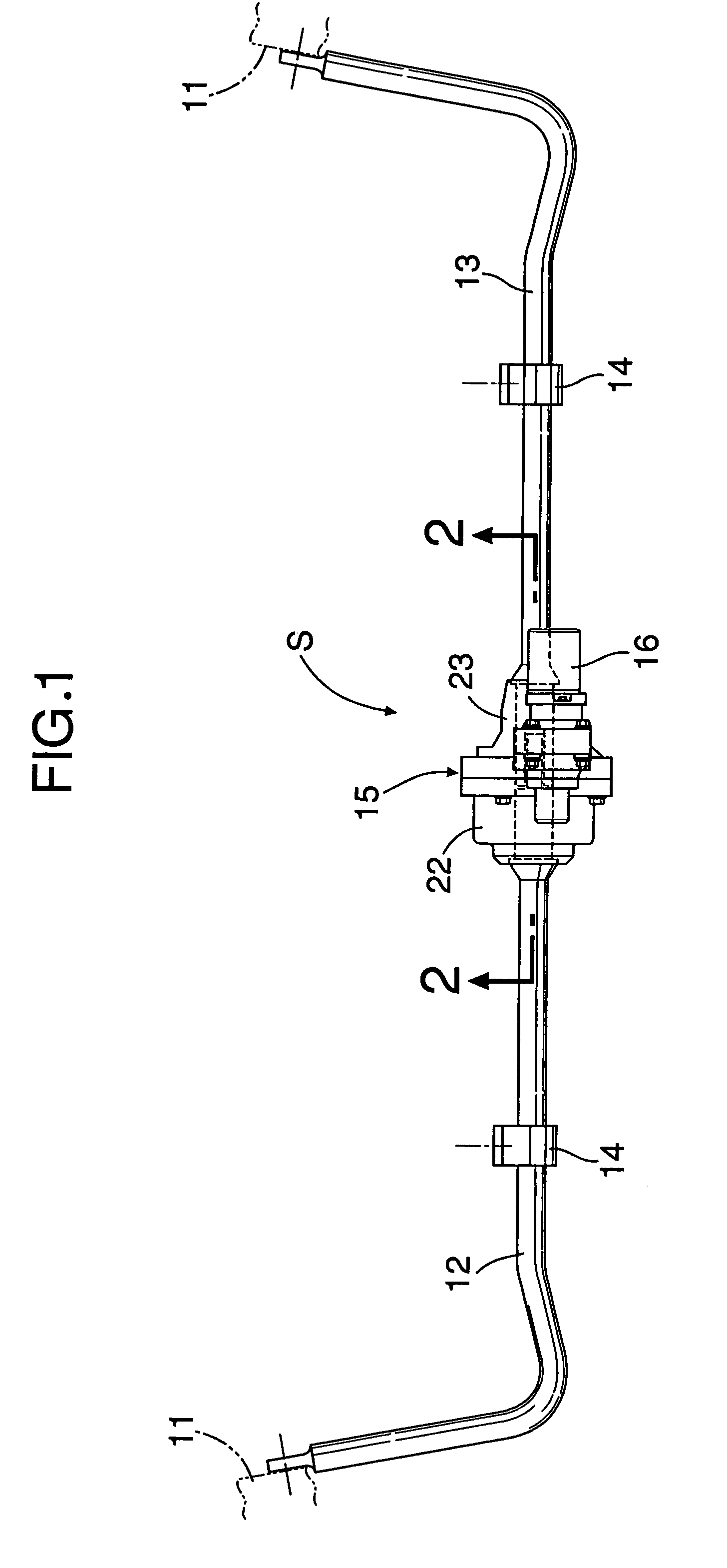
[0022]As shown in FIG. 1, a vehicular active stabilizer system S is divided into two halves along at its center in the vehicle width direction, and includes: left and right stabilizer halves 12, 13 having outer ends which are respectively connected to knuckles 11 for rotatably supporting right and left wheels; left and right supporting brackets 14 for supporting the stabilizer halves 12, 13 on a vehicle body; and an actuator 15 for connecting the inner ends of the left and right stabilizer halves 12, 13 to each other, the inner ends being opposed to each other in the vehicle width direction. A motor 16 may be integrally provided with the actuator 15 so as to serve as a driving source for the actuator 15.

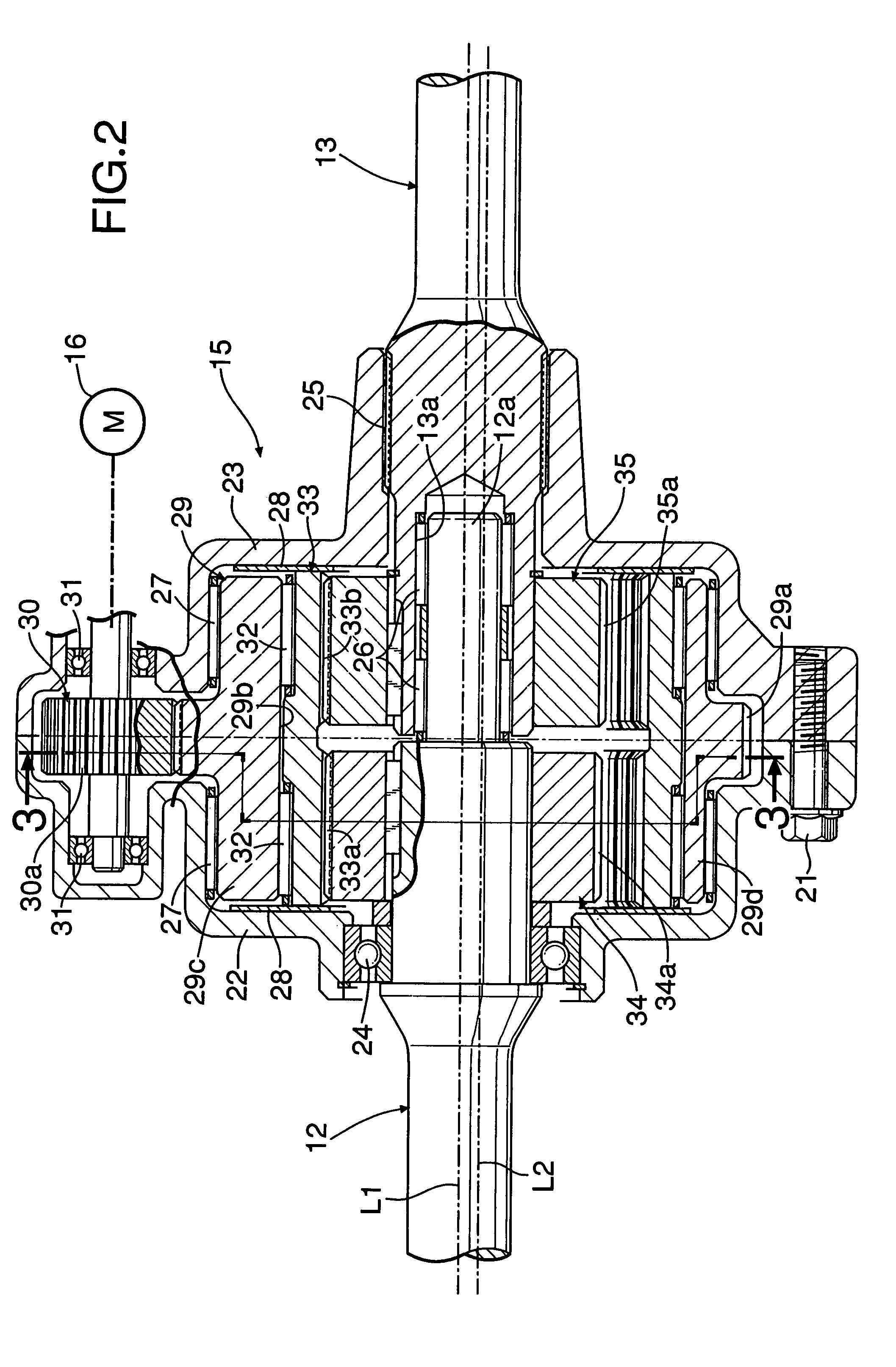
[0023]As shown in FIGS. 2 to 4, the actuator 15 includes a left housing 22 and a right housing 23 which are integrally coupled by a bolt 21. The left stabilizer half 12 is rotatably supported in the left housing 22 by a ball bearing 24. The right stabilizer half 13 is relatively non-...


PUM


Abstract

A reduction gear includes a rotatable carrier, a ring gear rotatably fitted in an offset supporting hole in the carrier, and first and second sun gears having first and second outer teeth meshed with first and second inner teeth of the ring gear, respectively. The rotation of the carrier is reduced in speed and outputted as relative rotation of the first and second sun gears. Thus, it is possible to secure a large reduction ratio although in a small structure having a small number of components. Also, it is possible to change the reduction ratio by a slight design change of the number of teeth in one or both of the outer teeth of the first and second sun gears, thereby improving the versatility.

Description

CROSS-REFERENCE TO RELATED APPLICATIONS[0001]The present claims priority from Japanese patent application 2006-346612, filed 22 Dec. 2006. The entire disclosure of each of the referenced priority documents is incorporated herein by reference.BACKGROUND OF THE INVENTION[0002]1. Field of the Invention[0003]The present invention relates to a reduction gear which outputs rotation of a carrier as relative rotation of first and second sun gears, and a vehicular active stabilizer system using the reduction gear.[0004]2. Description of the Background Art[0005]Japanese Patent Publication No. 2002-518245 discloses a device including a stabilizer whose opposite ends are connected to left and right suspension devices, and an actuator provided at an intermediate portion of the stabilizer. Left and right halves of the stabilizer are relatively twisted in opposite directions to control yaw moment of a vehicle. In this device, the actuator comprises three in-line-connected planetary gear mechanisms...

Claims


Application Information

Patent Timeline
Patent Type & Authority Patents(United States)
IPC IPC(8): B60G21/055F16H1/28
CPCB60G21/0555B60G2202/135F16H1/32B60G2204/419B60G2202/42
Inventor AZEKATSU, YOSHITOMOHAKUI, TAKEHIKOYUTA, ATSUSHI
Owner HONDA MOTOR CO LTD
Why Eureka
Try Eureka