Connector and a connector assembly

a technology of connectors and connectors, applied in the direction of live contact access prevention, coupling device connections, electrical equipment, etc., can solve the problems of deformation of the leading end of the male terminal fitting and the corner of the female housing

Inactive Publication Date: 2009-09-15
SUMITOMO WIRING SYST LTD
View PDF11 Cites 8 Cited by
  • Summary
  • Abstract
  • Description
  • Claims
  • Application Information

AI Technical Summary

Benefits of technology

[0008]The mating housing may be inserted into the receptacle in an improper posture oblique to a fitting direction while the moving plate is accommodated at the initial position in the receptacle. However, the corner of the mating housing will contact with the projecting end of the protection wall to prevent damage or deformation of the terminal fittings.
[0012]The protection wall preferably is arranged to surround a group of positioning holes. Thus, the main body is stronger and is not likely to be deformed plastically by external factors.

Problems solved by technology

However, a corner of the female housing can contact and deform the leading ends of the male terminal fittings if the female housing is inserted into the receptacle in an improper or inclined posture.

Method used


Image

  • Connector and a connector assembly
  • Connector and a connector assembly
  • Connector and a connector assembly

Examples


Embodiment Construction

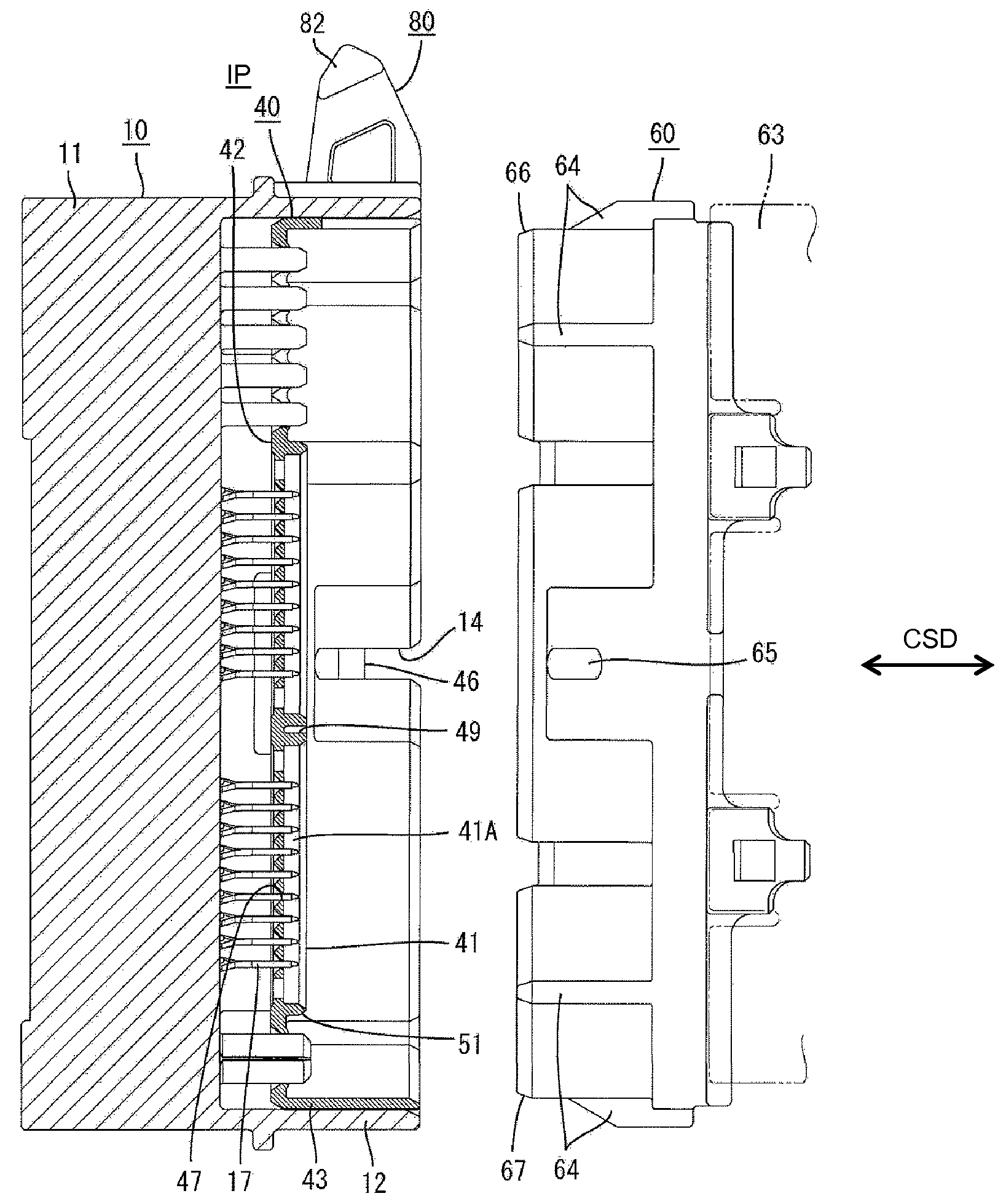
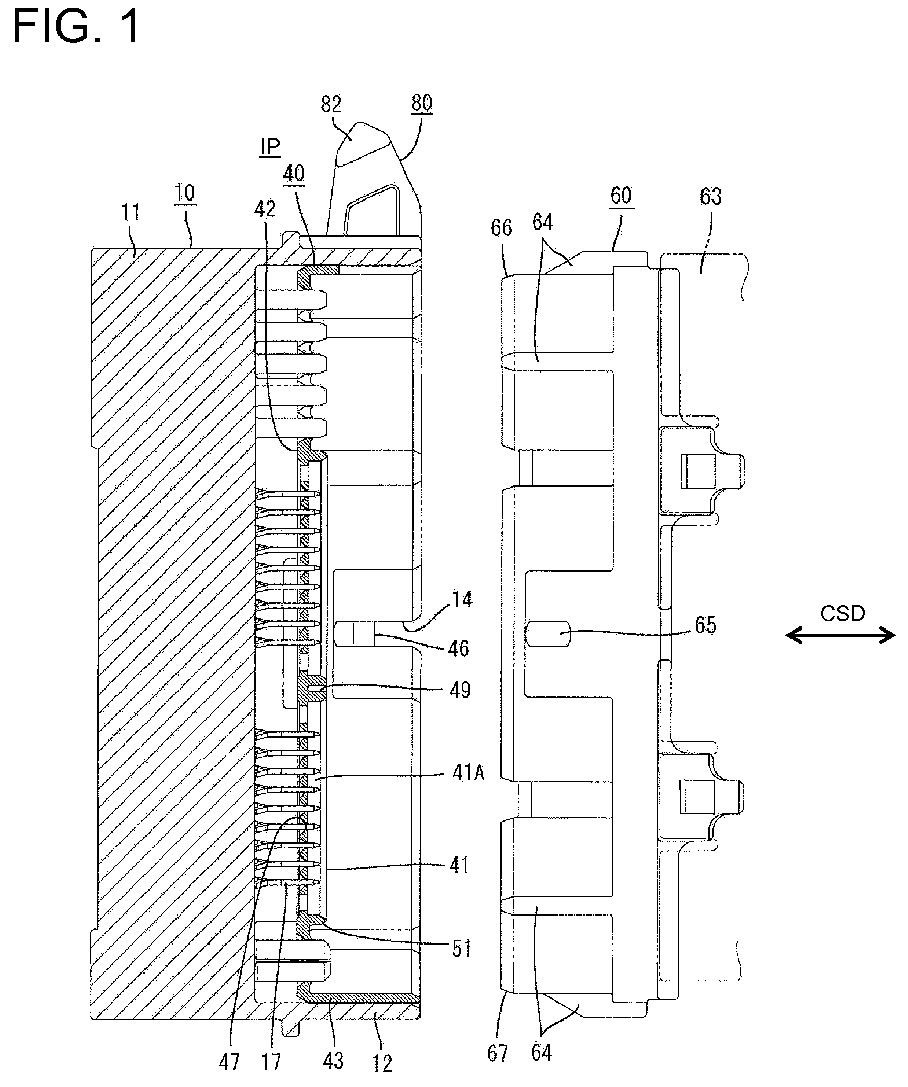
[0022]A connector assembly in accordance with the invention is illustrated in FIGS. 1 to 6. The connector assembly has a male housing 10 and a female housing 60 that are connectable with each other along connecting and separating directions CSD. Ends of the housings 10, 60 to be connected are referred to as the front ends in the following description.

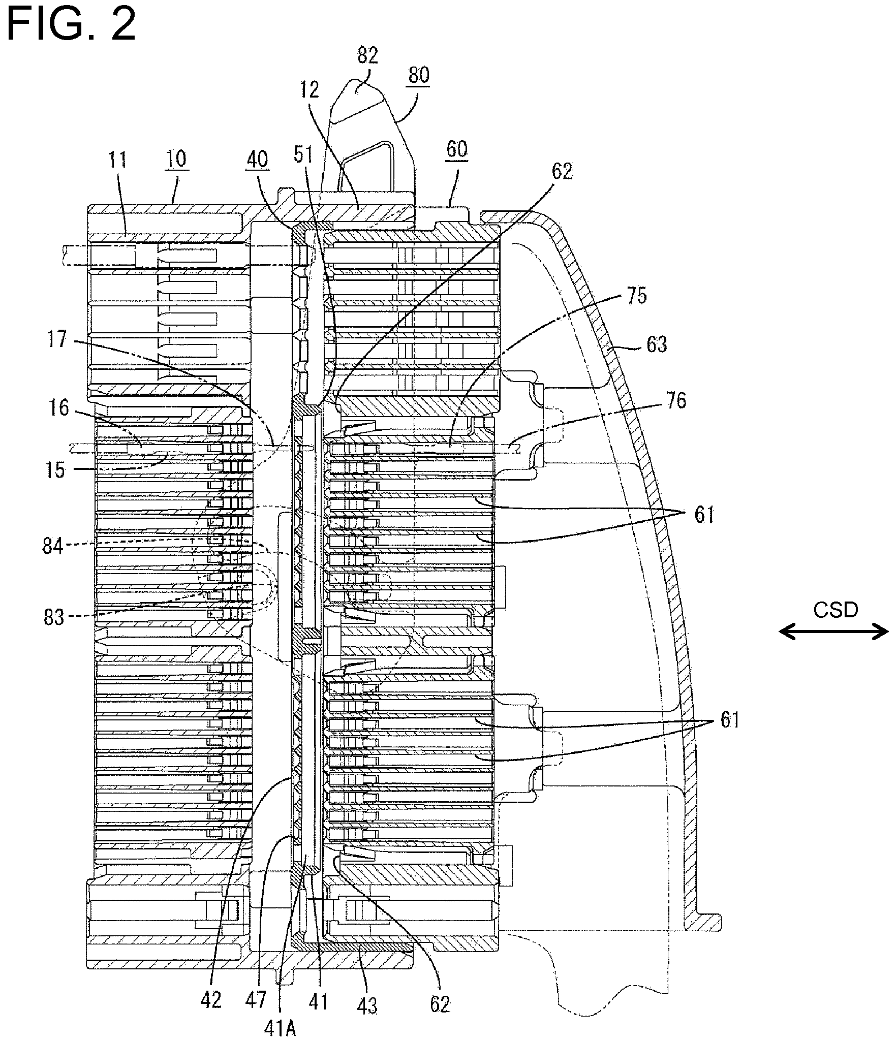
[0023]The female housing 60 is made e.g. of synthetic resin and is substantially in the form of a block that is long and narrow in the vertical direction in FIG. 1. Cavities 61 are formed substantially side by side in the female housing 60 and are arranged at several stages in the height direction of the female housing 60 as shown in FIG. 2. The cavities 61 are configured for accommodating female terminal fittings 75. The front openings of the cavities 61 are aligned in the front surface of the female housing 60. Substantially U-shape recesses 62 are formed in the front surface of the housing 60 around groups of the cavities 61. The rec...


PUM


Abstract

A connector includes a receptacle (12) and a moving plate (40) that can move in the receptacle (12) as a female housing (60) is fit into receptacle (12). The moving plate (40) includes a main body (42) with positioning holes (47) for receiving tabs (17) of male terminal fittings (15). Leading ends of the tabs (17) project through the positioning holes (47) when the moving plate (40) is at an initial position. A protection wall (41) projects forward from the main body (42) and prevents a corner (66) of an improperly aligned female housing (30) from contacting the leading ends of the tabs (17) when the moving plate (40) is at the initial position. The female housing (60) has recesses (62) for receiving the protection wall (41) when the female housing (60) is aligned properly.

Description

BACKGROUND OF THE INVENTION[0001]1. Field of the Invention[0002]The invention relates to a connector and to a connector assembly.[0003]2. Description of the Related Art[0004]U.S. Patent Application Publication No. 2006-0154505 discloses a connector with a male housing that has a forwardly open tubular receptacle and male terminal fittings that project into the receptacle. The connector also includes a female housing that can fit into the receptacle from the front. A moving plate is accommodated in the receptacle and is movable in forward and backward directions. The moving plate includes a plate-like main body formed with positioning holes. The leading ends of male terminal fittings are inserted through the positioning holes to project from the front surface of the main body before the male housing is connected with the female housing. An electrical connection test is performed at this initial position by pressing a probe pin against the leading ends of the male terminal fittings pr...

Claims


Application Information

Patent Timeline
Patent Type & Authority Patents(United States)
IPC IPC(8): H01R13/44
CPCH01R13/62933H01R13/4538
Inventor KOBAYASHI, YUTAKA
Owner SUMITOMO WIRING SYST LTD
Why Eureka
Try Eureka