Liquid ejection head

a liquid ejection and head technology, applied in the field of liquid ejection heads, can solve the problems of high probability of density unevenness, inability to accurately measure the size of the trailing part, and prone to mist floating, etc., and achieve the effect of stably affecting the density

Inactive Publication Date: 2009-09-22
CANON KK
View PDF4 Cites 22 Cited by
  • Summary
  • Abstract
  • Description
  • Claims
  • Application Information

AI Technical Summary

Benefits of technology

[0015]In view of the above-described circumstances, an object of the present invention is to provide a liquid ejection head that stably ejects droplets at a high driving frequency using a dense nozzle arrangement to allow main droplets and satellites to stably impact a print medium, while preventing bubbles from remaining in a common liquid chamber.
[0016]The present invention can provide the liquid ejection head that stably ejects the droplets at the high driving frequency using the dense nozzle arrangement to allow the main droplets and the satellites to stably impact the print medium, while preventing the bubbles from remaining in the common liquid chamber.

Problems solved by technology

Consequently, these trailing parts, called satellites, are inappropriately small and are prone to become mist floating inside a printer housing instead of impacting a print medium.
As a result, a position on the print medium at which each satellite impacts the print medium varies, resulting in the high likelihood of density unevenness.
Images obtained by printing are thus prone to suffer density unevenness.
Since the ink to be ejected is fed from the opposite sides of the ejection ports to the ejection ports, a possible one-sided ink flow is inhibited which may affect the growth of bubbles when the ink is ejected.
Thus, the trailing of the ejected ink is prone to be straight, short, and thick.
As a result, satellites formed by breakage of the trailing during the process of formation of droplets are prone to be large.
Therefore, even if printing is performed at a high speed or with small droplets, density unevenness is unlikely to occur.
As a result, density unevenness is unlikely to occur in images obtained on the print medium.
However, the ink in the common liquid chamber which is positioned away from the supply pipes is unlikely to flow even with suction recovery.
Thus, the ink stored in this site is prone to remain instead being sucked.
Consequently, bubbles are prone to remain in the site and may affect ink ejection.
This makes it difficult to maintain the appropriate ejection condition of the print head and to stabilize ejection.
This reduces the throughput of a printing apparatus using this print head.
However, the increased diameter of the hole increases the size of each of the pressure chambers and thus the distance between each ejection port and thus between each ejected droplet.
The reduced resolution finally reduces the throughput of the printing apparatus.
Furthermore, the reduced thickness of the layer reduces the amount of heat externally diffused via the layer and thus the amount of heat radiated.
Thus, heat generated by the heater cannot be sufficiently released.
Therefore, also in this case, the throughput cannot be improved.

Method used


Image

  • Liquid ejection head
  • Liquid ejection head
  • Liquid ejection head

Examples


first embodiment

[0031]A first embodiment for carrying out the present invention will be described with reference to the attached drawings.

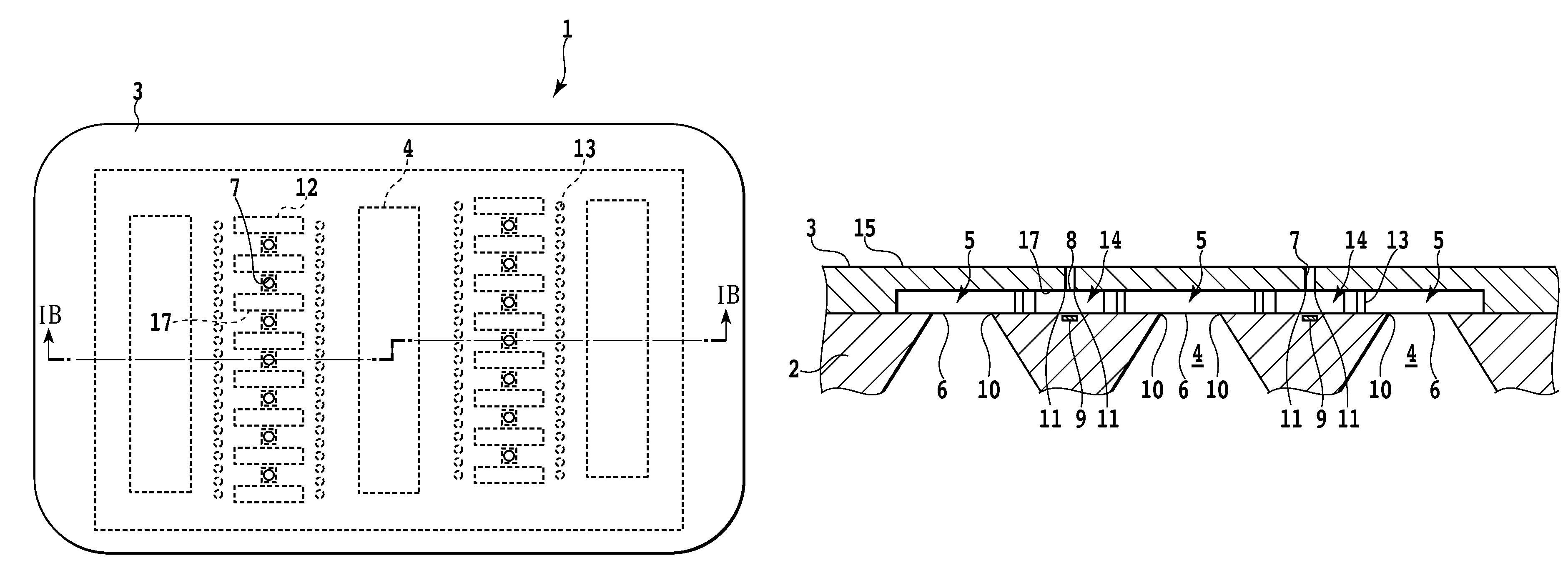
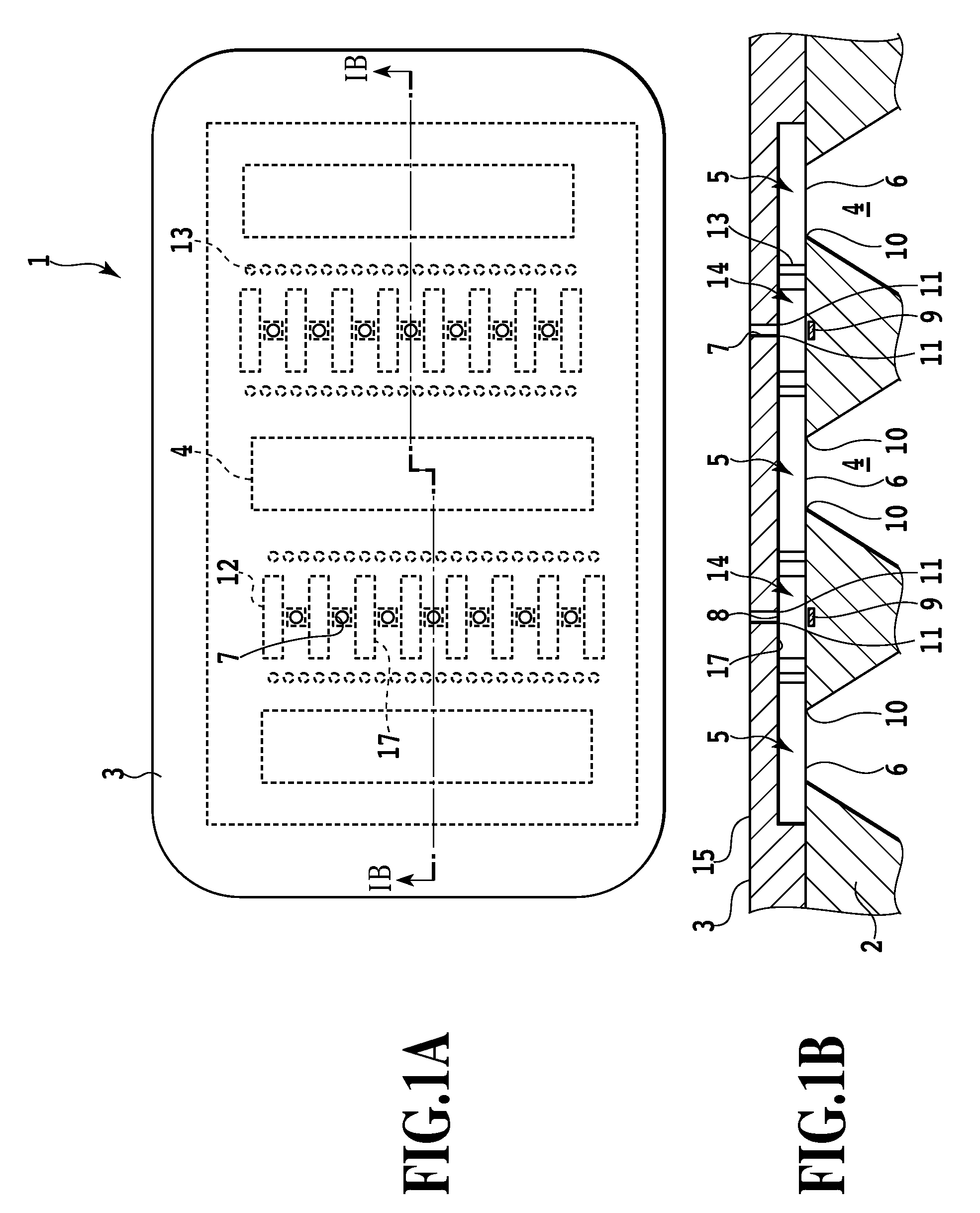
[0032]FIG. 1A is a plan view of a print head 1 as a liquid ejection head according to a first embodiment of the present invention. FIG. 1B is a sectional view of the print head taken along line IB-IB in FIG. 1A. In a print head according to the present embodiment, an orifice plate 3 is joined to a substrate 2. FIG. 1A shows a plan view of the orifice plate 3.

[0033]Ink supply ports 4 are formed as liquid supply ports in the substrate 2 so as to penetrate the substrate 2 from a back surface to a front surface thereof; ink is introduced into the print head 1 through the ink supply ports 4. To be fed to the interior of each of the ink supply ports 4 and thus into the print head 1, the ink is fed through the ink supply port 4 from the back surface to front surface of the substrate 2. In the present embodiment, the three ink supply ports 4 are formed along line IB-IB. ...

second embodiment

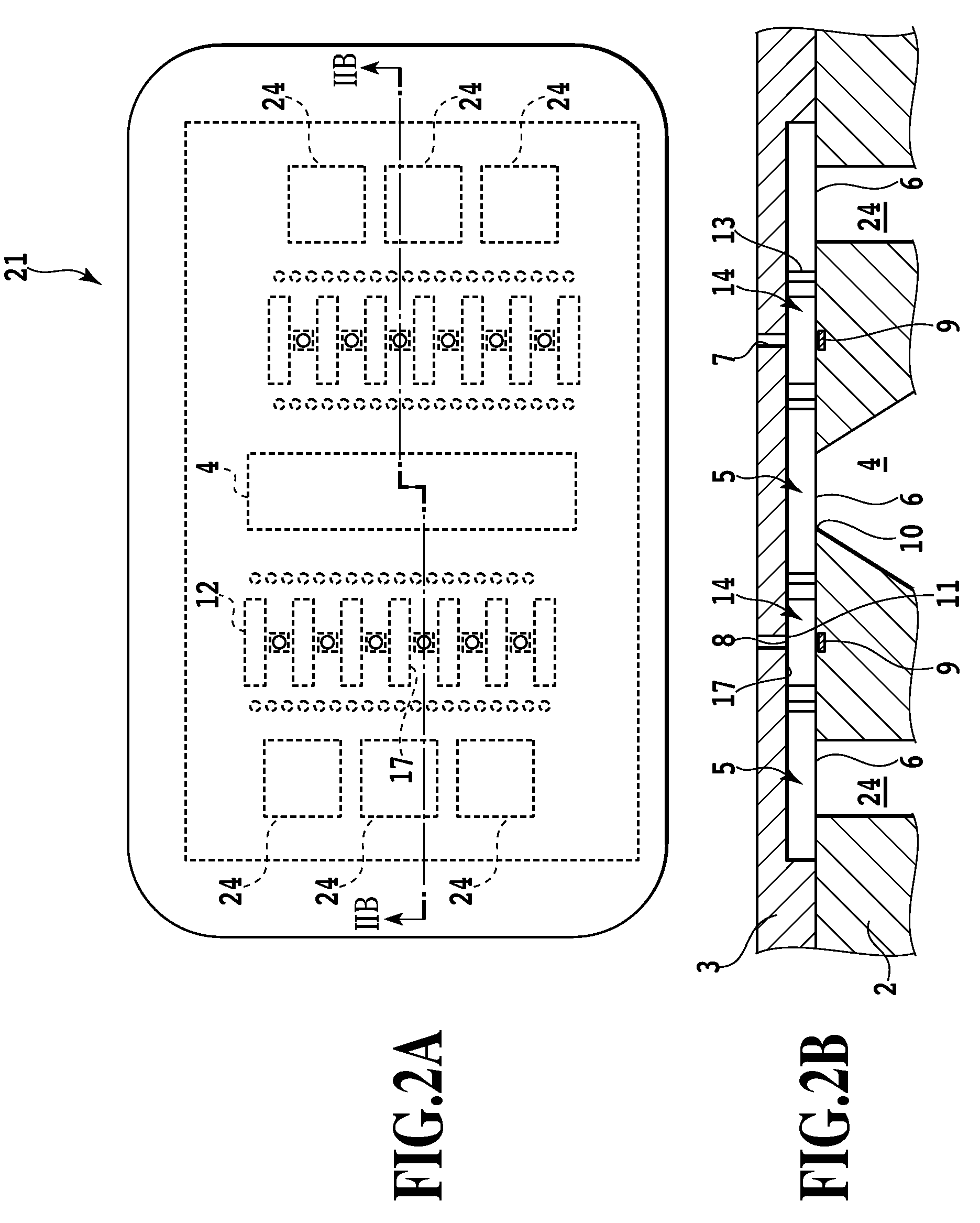
[0047]Now, a second embodiment will be described with reference to FIGS. 2A and 2B. In the figures, parts of the second embodiment which can be configured similarly to the corresponding ones of the first embodiment are denoted by the same reference numerals as those in the first embodiment. The description of these parts is omitted, and only the differences from the first embodiment will be described below.

[0048]FIG. 2A is a plan view of a print head 21 according to the second embodiment. FIG. 2B is a sectional view of the print head 21 taken along line IIB-IIB shown in FIG. 2A.

[0049]In the print head 1 according to the first embodiment, the three rows of the ink supply ports all extend in the same direction as that in which the row of the ejection ports extends and are formed continuously all over the length of the ink supply port in the longitudinal direction. In contrast, in the print head 21 according to the second embodiment, a plurality of segmented ink supply ports 24 are for...

third embodiment

[0056]Now, a third embodiment will be described with reference to FIGS. 3A and 3B. In the figures, parts of the third embodiment which can be configured similarly to the corresponding ones of the first and second embodiments are denoted by the same reference numerals as those in the first and second embodiments. The description of these parts is omitted, and only the differences from the first and second embodiments will be described below.

[0057]FIG. 3A is a plan view of a print head 31 according to the third embodiment. FIG. 3B is a sectional view of the print head 31 taken along line IIIB-IIIB shown in FIG. 3A.

[0058]In the first embodiment, described above, the three rows of the ink supply ports all extend in the same direction as that in which the row of the ejection ports extends and are formed continuously all over the length of the ink supply port in the longitudinal direction. Furthermore, in the second embodiment, the outside ones of the plurality of ink supply ports are eac...


PUM


Abstract

A print head that ejects ink supplied through an ink supply port can prevent the size of satellites from being reduced while inhibiting an increase in resistance to an ink flow. In the print head, ink supply ports are arranged on both sides of a plurality of channels. A predetermined number of ink supply ports are arranged at least one side of the ink channel all over the range of the arrangement of the channels. One side of each of the plurality of channels is connected via the common liquid chamber to the liquid supply port located so as to extend in a direction in which the channels are arranged.

Description

BACKGROUND OF THE INVENTION[0001]1. Field of the Invention[0002]The present invention relates to a liquid ejection head that supplies energy to ejection energy generating elements to provide the energy to the liquid to eject the liquid through ejection ports.[0003]2. Description of the Related Art[0004]In many ink jet printing apparatuses commonly used, a print head as a liquid ejection head has been formed by laminating an orifice plate to a substrate with liquid supply ports and the like formed therein, from the past. The structure of such a print head is shown in FIGS. 11A and 11B. FIG. 11A shows a plan view of a conventional liquid ejection head 501. FIG. 11B shows a sectional view of the conventional liquid ejection head 501 taken along line XIB-XIB in FIG. 11A. In this form of print head, the substrate 503 and the orifice plate 502 are laminated together to form a common liquid chamber 504 in a part of the space between the substrate 503 and the orifice plate 502. A liquid sup...

Claims


Application Information

Patent Timeline
Patent Type & Authority Patents(United States)
IPC IPC(8): B41J2/15B41J2/145
CPCB41J2/1404B41J2/14145B41J2002/14467B41J2002/14403B41J2002/14387
Inventor TSUCHII, KENSAKURAI, MASATAKAINOUE, TOMOYUKISAITO, AKIKO
Owner CANON KK
Why Eureka
Try Eureka