
Spiral link fabric and methods to build the same

a technology of spiral link fabric and fabric, applied in the field of spiral link fabrics, can solve the problems of spiral link fabric labor-intensive and expensive production, spiral link fabric wears out and requires replacement, and the cost of the process is high

Active Publication Date: 2009-09-22
ALBANY INT CORP
View PDF16 Cites 2 Cited by
  • Summary
  • Abstract
  • Description
  • Claims
  • Application Information

AI Technical Summary

Benefits of technology

The present invention is a special fabric used in papermaking machines that has intertwined coils. These coils are connected in a pattern that looks like chain mail, without needing to be fastened. The fabric is made up of alternating sets of coils that are connected by interdigitating loops and inserting parallel pins. The loops on the coils can be spaced by mechanically spreading or tentering them during finishing, or by inserting spacers between them. The technical effect of this invention is to improve the efficiency and quality of papermaking by improving the drainage and retention of paper pulp.

Problems solved by technology

These fabrics wear out and require replacement.
Unfortunately, the production of spiral-link fabrics is both labor-intensive and expensive.
The multiple manufacturing steps of coiling, interdigitating, and interconnecting the spiral coils make this process costly.
In addition, the shape of the coil loops results in such close spacing when interdigitated (i.e. almost touching) that the pintles are almost entirely covered.
However, this stiffness can be detrimental if, for example, any of the support rolls or dryer cans in a dryer section are not all parallel to one another.
This lack of diagonal ‘give’ can then cause the spiral-link fabric to edge-up and / or to guide poorly, eventually damaging the edges of the fabric as it contacts guards, frames, etc. . . . and eventually leading to premature replacement.

Method used


Image

  • Spiral link fabric and methods to build the same
  • Spiral link fabric and methods to build the same
  • Spiral link fabric and methods to build the same

Examples


Embodiment Construction

[0028]A preferred embodiment of the present invention will be described in the context of a spiral-link fabric for use in a papermachine, as well as in other industrial settings.

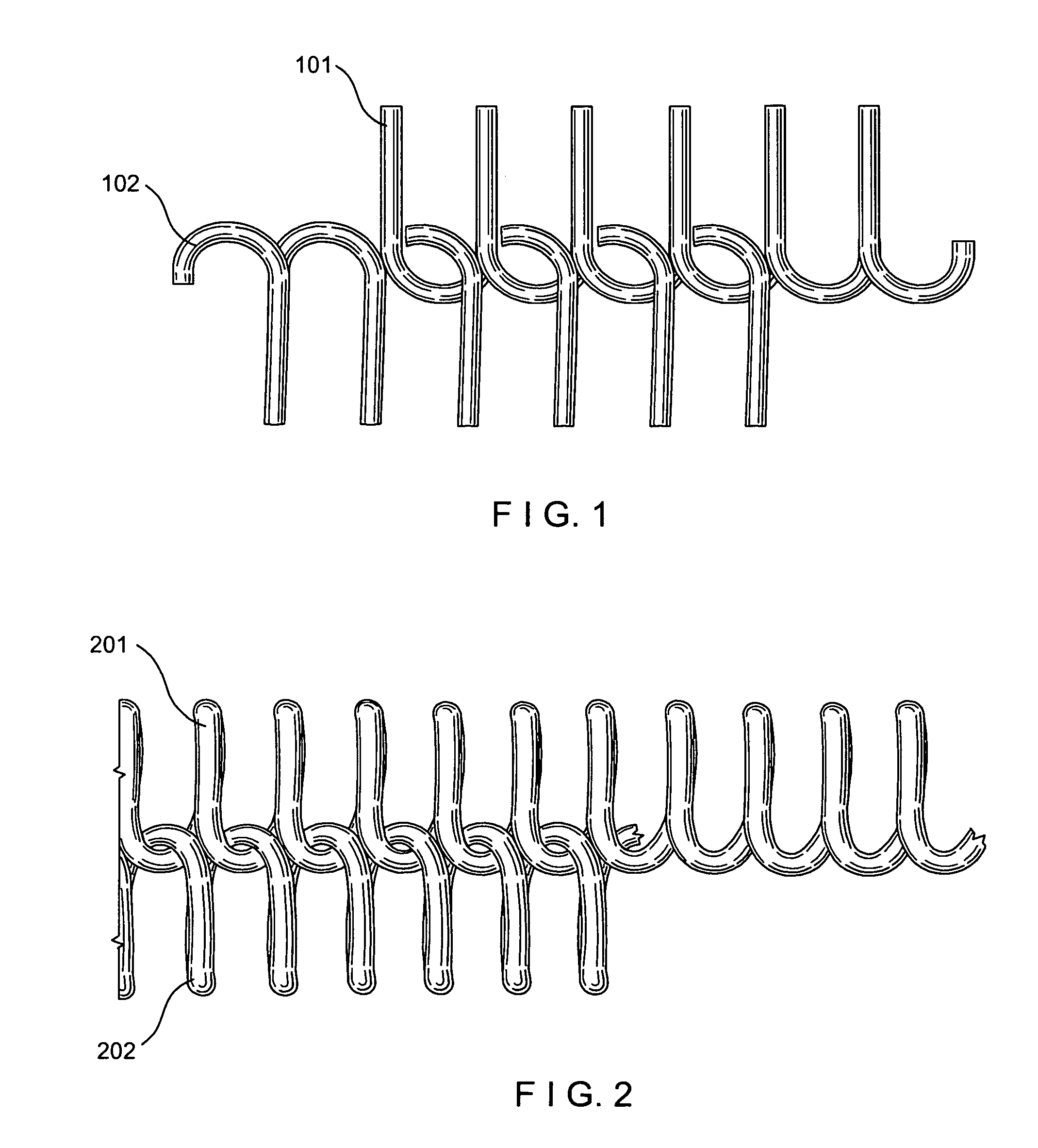
[0029]FIG. 1 is a diagram showing the “chain mail” intertwining of two right-turn spiral coils in accordance with the teachings of the present invention. The term “chain mail” refers to the intertwined loop pattern which is similar to that found in armor. The top right-turn coil 101 is intertwined with the bottom right-turn coil 102. Importantly, the loops of the two spiral coils may be in an almost parallel alignment; as opposed to the distinct angle formed by the prior art coils (see FIG. 5). Note the intertwined loops in this “chain mail” pattern do not require a pintle to connect the coils although one could be inserted if so desired.

[0030]FIG. 2 is a picture of the “chain mail” intertwining of two right-turn spiral coils in accordance with the teachings of the present invention. As in FIG. 1, the top ri...


PUM


Abstract

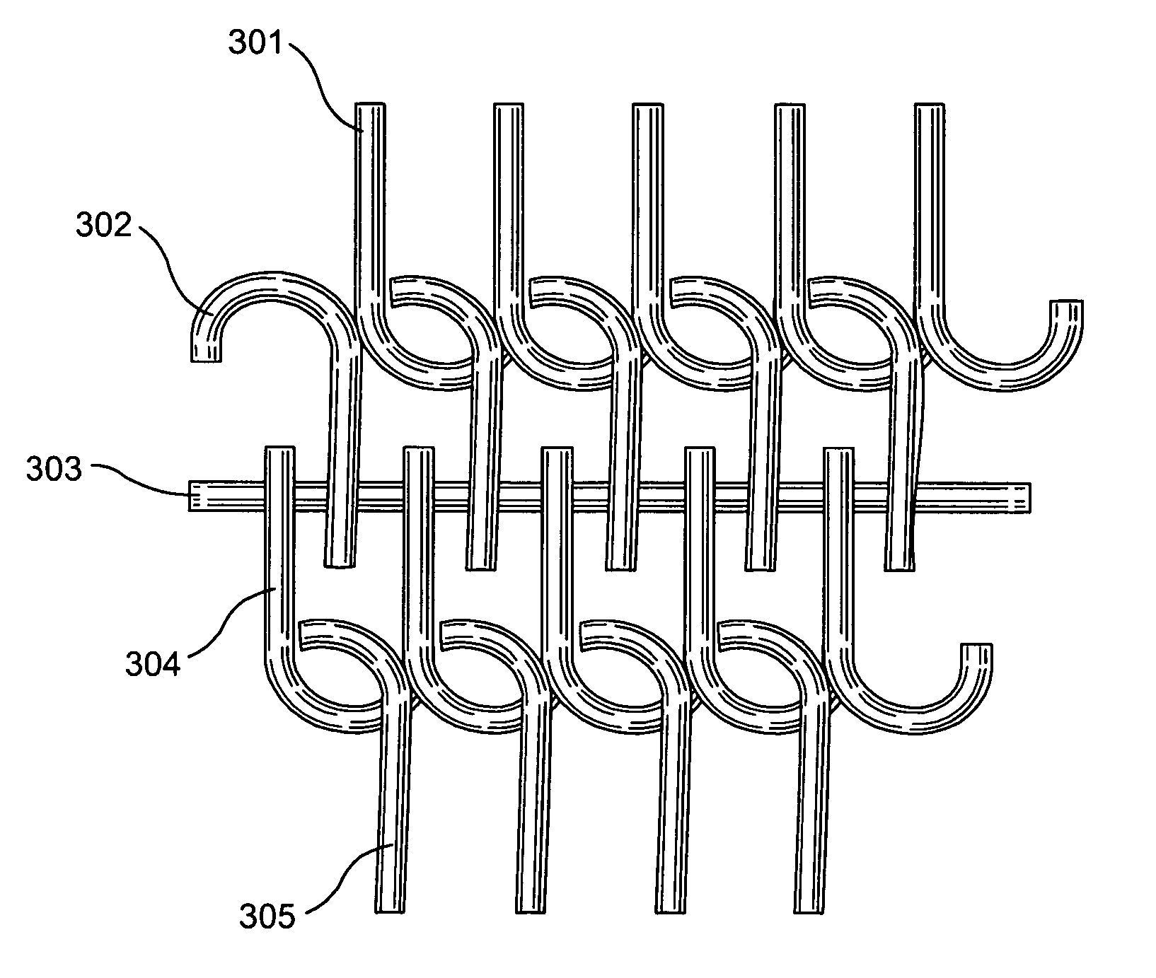
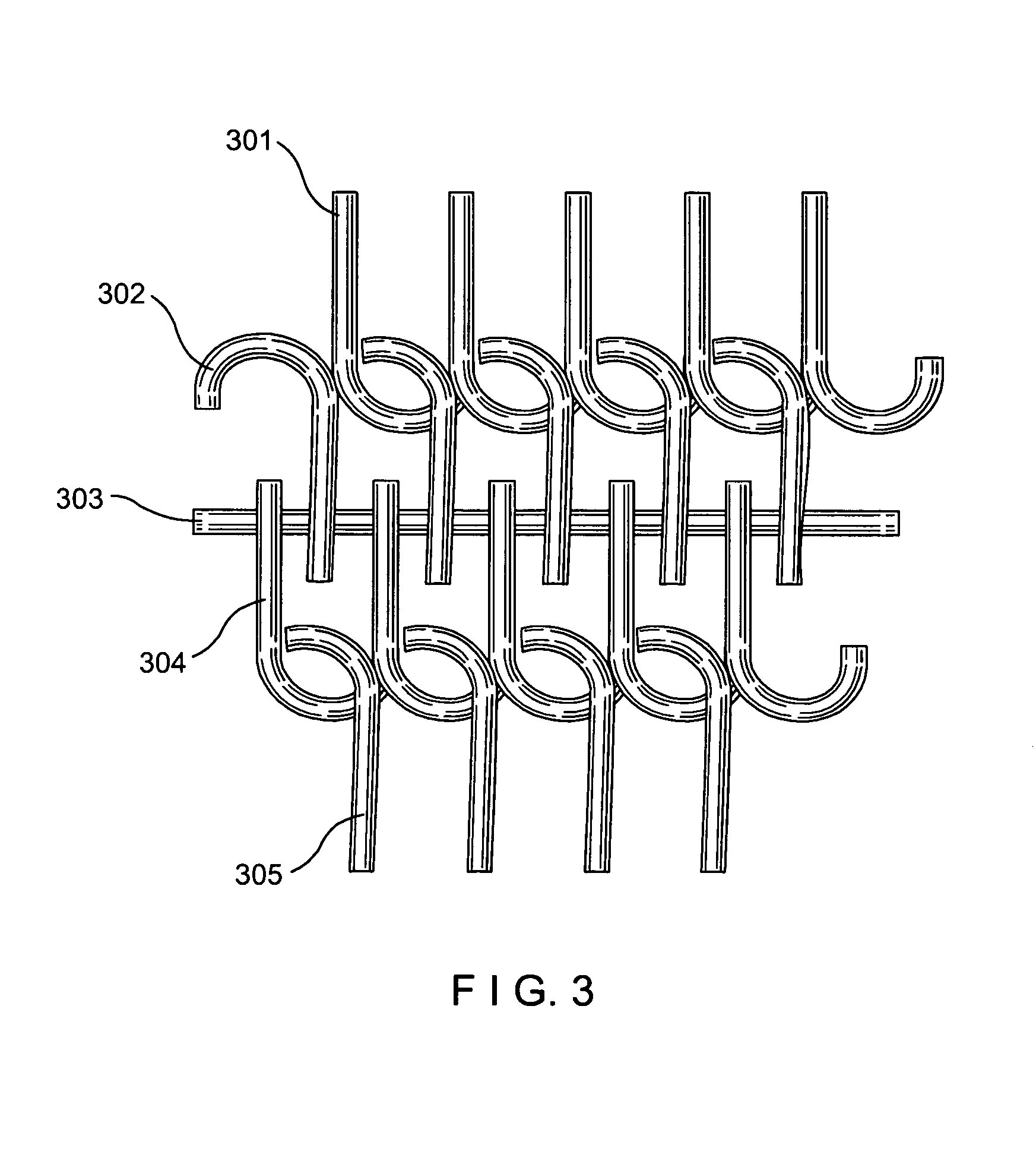
A spiral-link fabric comprised of connected sets of “chain mail” intertwined spiral coils. Alternating sets of two right-turn spiral coils and two left-turn spiral coils are repeatedly connected to form the body of the fabric. Within each set, the spiral coil loops are intertwined in a pattern which does not require fastening to connect the coils. The alternating sets are connected by interdigitating respective spiral coil loops and inserting a series of parallel pintles extending through the channels formed by the interdigitated loops.

Description

CROSS-REFERENCE TO RELATED APPLICATIONS[0001]This application claims priority benefits of U.S. Provisional Patent Application Ser. No. 60 / 713,095 filed Aug. 31, 2005 entitled “Improved Spiral Fabric and Methods to Build the Same”, the disclosure of which is incorporated herein by reference.BACKGROUND OF THE INVENTION[0002]1. Field of the Invention[0003]The present invention relates to spiral-link fabrics. More specifically, the present invention relates to spiral-link fabrics having “chain mail” intertwined coils for use on a papermaking machine and other industrial machines requiring fabrics / belts.[0004]2. Description of the Related Art[0005]While the use of this fabric will be described for the papermaking process, other industrial uses exist; such as belts / fabrics for DNT (double nip thickener) machines, sludge dewatering presses, bowling pin spotter belts, and in the production of certain nonwoven products by processes such as, but not limited to, hydroentangling (spunlace), spu...

Claims


Application Information

Patent Timeline
Patent Type & Authority Patents(United States)
IPC IPC(8): D21F1/10D21F7/08D21F7/12B21F27/18
CPCD21F1/0072Y10S162/90Y10S162/903Y10T428/249922D21F1/00
Inventor BILLINGS, ALAN L.GARDNER, CURTIS L.
Owner ALBANY INT CORP
Learn More