Image generating apparatus

a technology of image generating apparatus and generating apparatus, which is applied in the direction of typewriters, power drive mechanisms, instruments, etc., can solve the problems of disadvantageous increase in number of components

Inactive Publication Date: 2009-09-22
FUNAI ELECTRIC CO LTD
View PDF9 Cites 2 Cited by
  • Summary
  • Abstract
  • Description
  • Claims
  • Application Information

AI Technical Summary

Benefits of technology

[0015]The present invention has been proposed in order to solve the aforementioned problems, and an object of the present invention is to provide an image generating apparatus capable of keeping the position of a shaft without increasing the number of components.
[0016]An image generating apparatus according to a first aspect of the present invention comprises a chassis detachably mounted with an ink sheet cartridge storing an ink sheet and integrally provided with a first bearing, a print head rotatably mounted on the chassis, a print head pressing member, including a shaft held by the first bearing, pressing the print head, a cartridge stop member provided on a first side surface of the chassis for engaging with the ink sheet cartridge thereby preventing the ink sheet cartridge from slipping off the chassis and a side plate, provided on a second side surface of the chassis, integrally including at least a second bearing of a paper feed roller, while the cartridge stop member provided on the first side surface of the chassis integrally includes a first shaft stop portion coming into contact with a first end surface of the shaft of the print head pressing member, and the side plate provided on the second side surface of the chassis integrally includes a second shaft stop portion coming into contact with a second end surface of the shaft of the print head pressing member.

Problems solved by technology

In the thermal transfer sheet cassette described in the aforementioned Japanese Patent Laying-Open No. 2005-219310, however, the coil spring and the two cylindrical members must be separately provided in order to keep the position of the take-up core, whereby the number of components is disadvantageously increased.
In the thermal printer described in the aforementioned Japanese Patent Laying-Open No. 2004-114588, the fixture must be separately provided in order to keep the position of the shaft, whereby the number of components is disadvantageously increased.
In the image generating apparatus described in the aforementioned Japanese Patent Laying-Open No. 2001-271826, the two clasps must be separately provided in order to keep the position of the paper feed support shaft, whereby the number of components is disadvantageously increased.
In the image generating apparatus described in the aforementioned Japanese Patent Laying-Open No. 06-317975, the slide bearing must be separated in order to support the roller shaft, whereby the number of components is disadvantageously increased.
In the image generating apparatus described in the aforementioned Japanese Patent Laying-Open No. 08-225182, the two bearings and the wire spring must be separately provided respectively in order to keep the position of the transport roller, whereby the number of components is disadvantageously increased.

Method used


Image

  • Image generating apparatus
  • Image generating apparatus
  • Image generating apparatus

Examples


first embodiment

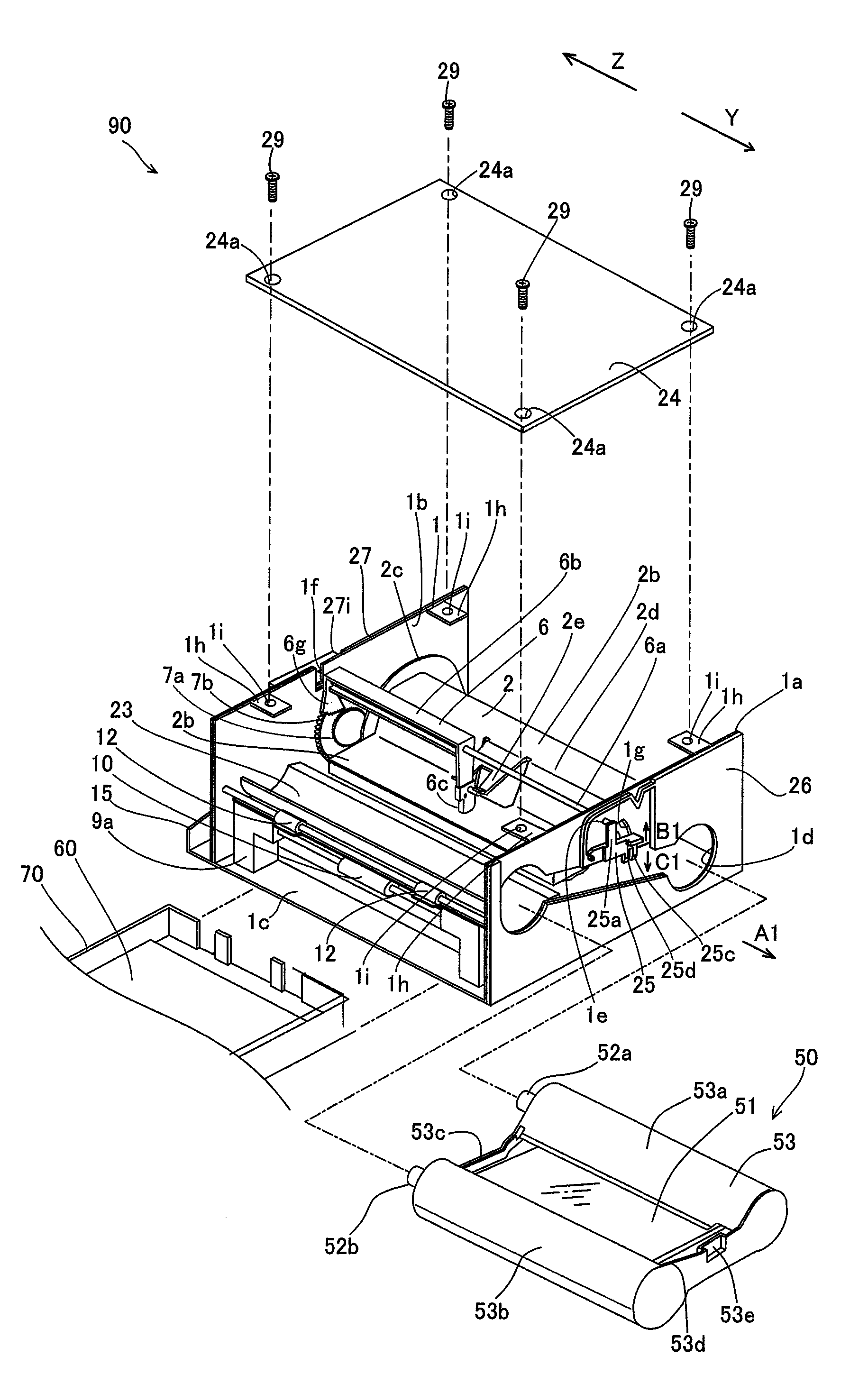
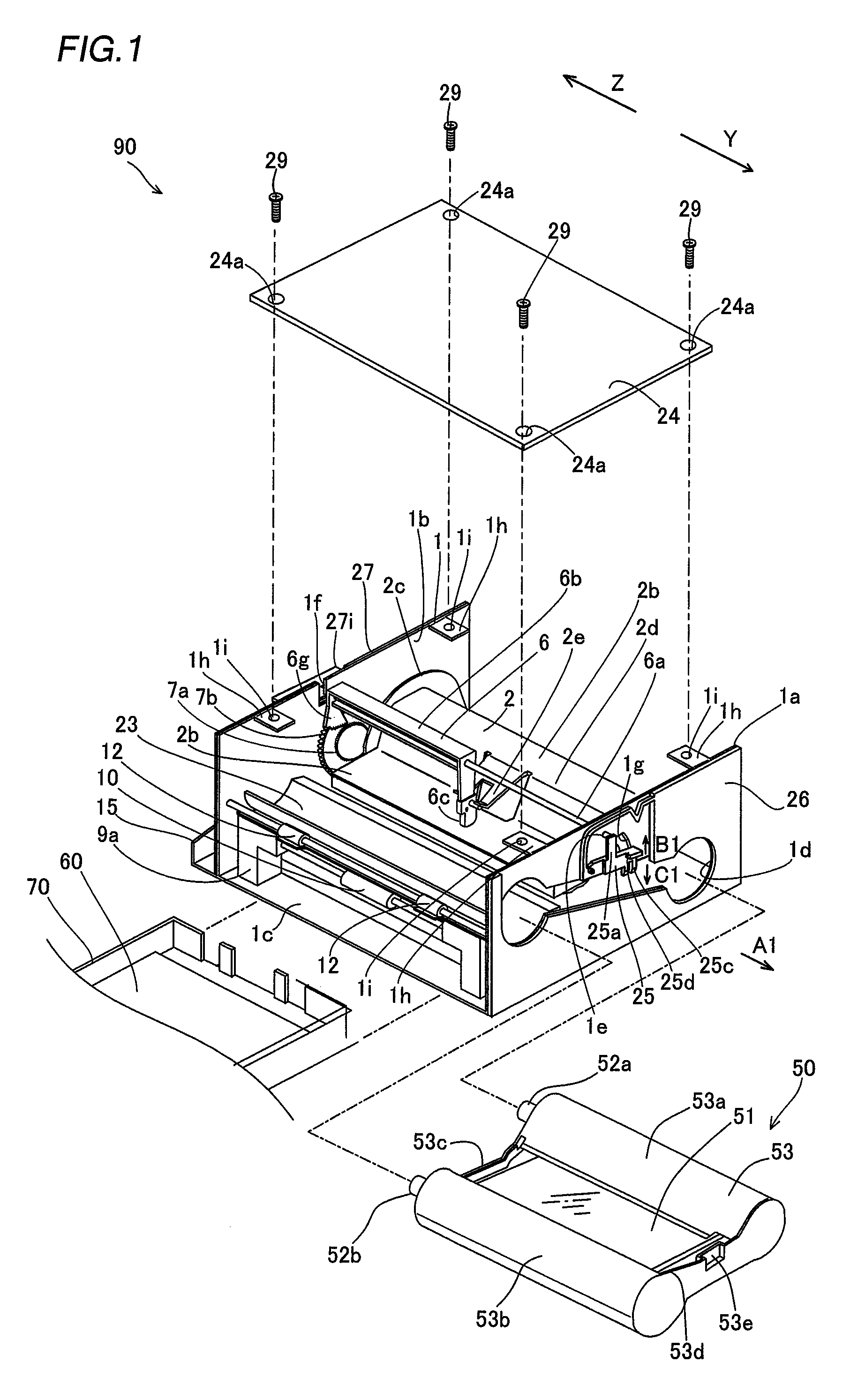
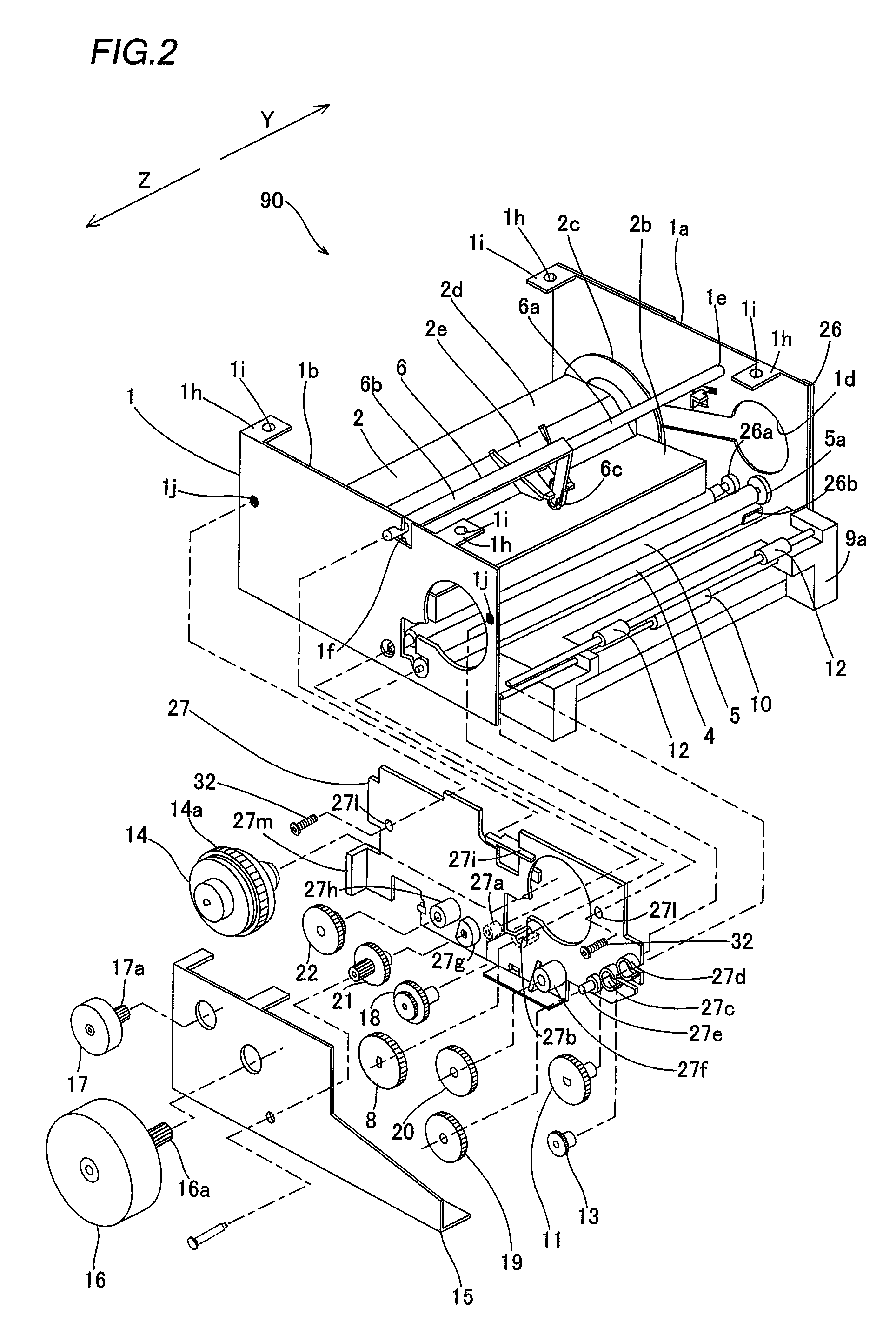
[0060]First, the structure of a sublimatic printer 90 according to a first embodiment of the present invention is described with reference to FIGS. 1 to 22. According to the first embodiment, the present invention is applied to the sublimatic printer 90 employed as an exemplary image generating apparatus.

[0061]As shown in FIG. 1, the sublimatic printer 90 according to the first embodiment of the present invention comprises a chassis 1 of metal (sheet metal), a print head 2 for printing images, a platen roller 3 (see FIG. 5) opposed to the print head 2, a feed roller 4 (see FIG. 5) of metal, a press roller 5 (see FIG. 5) of metal pressing the feed roller 4 with prescribed pressing force, a print head pressing member 6, including a shaft 6a, pressing the print head 2, a driving gear 7 (see FIG. 4) of resin constituted of a small-diametral gear 7a and a large-diametral gear 7b, a feed roller gear 8 (see FIGS. 2 and 6), a lower paper guide 9a of resin, an upper paper guide 9b (see FIG. ...

second embodiment

[0093]The structure of a sublimatic printer 100 according to a second embodiment of the present invention is described with reference to FIGS. 24 to 29. In the sublimatic printer 100 according to the second embodiment, a rotational portion 102 of a print head pressing member 101 is made of not metal but resin, dissimilarly to the sublimatic printer 90 according to the aforementioned first embodiment.

[0094]The sublimatic printer 100 according to the second embodiment comprises the print head pressing member 101, including a shaft 6a, pressing a print head 2, as shown in FIG. 24.

[0095]The print head 2 includes a heat radiating member 103 for radiating heat from a head portion 2b, as shown in FIG. 24.

[0096]According to the second embodiment, the print head pressing member 101 is constituted of the shaft 6a of metal and the rotational portion 102 of resin, as shown in FIGS. 24 and 25. A pressing portion 102a and a sectorial gear portion 102b are integrally provided on longitudinal ends ...


PUM


Abstract

This image generating apparatus includes a chassis and a side plate, a cartridge stop member provided on a first side surface of the chassis integrally has a first shaft stop portion coming into contact with a first end surface of a shaft of a print head pressing member, and a side plate provided on a second side surface of the chassis integrally has a second shaft stop portion coming into contact with a second end surface of the shaft of the print head pressing member.

Description

BACKGROUND OF THE INVENTION[0001]1. Field of the Invention[0002]The present invention relates to an image generating apparatus.[0003]2. Description of the Background Art[0004]An image generating apparatus comprising various rotating shafts are known in general, as disclosed in each of Japanese Patent Laying-Open Nos. 2005-219310, 2004-114588, 2001-271826, 06-317975 (1994) and 08-225182 (1996), for example.[0005]The aforementioned Japanese Patent Laying-Open No. 2005-219310 discloses a thermal transfer sheet cassette (ink sheet cartridge) comprising a columnar take-up core for taking up a thermal transfer sheet (ink sheet) and a take-up core holding portion. In the thermal transfer sheet cassette described in Japanese Patent Laying-Open No. 2005-219310, two cylindrical members are inserted into both ends of the take-up core, while a coil spring is set in the cylindrical member provided on one of the ends of the take-up core. The coil spring and the two cylindrical members keep the po...

Claims


Application Information

Patent Timeline
Patent Type & Authority Patents(United States)
IPC IPC(8): B41J2/32B41J29/00
CPCB41J17/32B41J35/28B41J29/02
Inventor SAWAI, KUNIONAITO, TAKAHIRO
Owner FUNAI ELECTRIC CO LTD
Why Eureka
Try Eureka