Method for determining a test strip calibration code for use in a meter
What is AI technical title?
AI technical title is built by Patsnap AI team. It summarizes the technical point description of the patent document.
a technology for calibration codes and test strips, applied in the field of methods, systems, test strips, calibration strips, etc., can solve the problems of inconvenient user use, time-consuming manual input or selection of calibration codes, and inaccurate and/or inaccurate determination of analy
Active Publication Date: 2009-09-22
LIFESCAN IP HLDG LLC
View PDF16 Cites 106 Cited by
Summary
Abstract
Description
Claims
Application Information
AI Technical Summary
This helps you quickly interpret patents by identifying the three key elements:
Problems solved by technology
Method used
Benefits of technology
Problems solved by technology
Failure to enter or select the calibration code that corresponds to a test strip undergoing use (i.e., the “correct” calibration code) can lead to inaccurate and / or imprecise determination of an analyte.
Moreover, the manual entering or selecting of calibration codes is time consuming and can be inconvenient to a user.
Method used
Image
Click on the blue label to locate the original text in one second.
Reading with bidirectional positioning of images and text.
Examples
Embodiment Construction
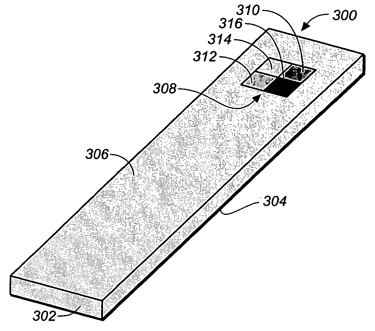
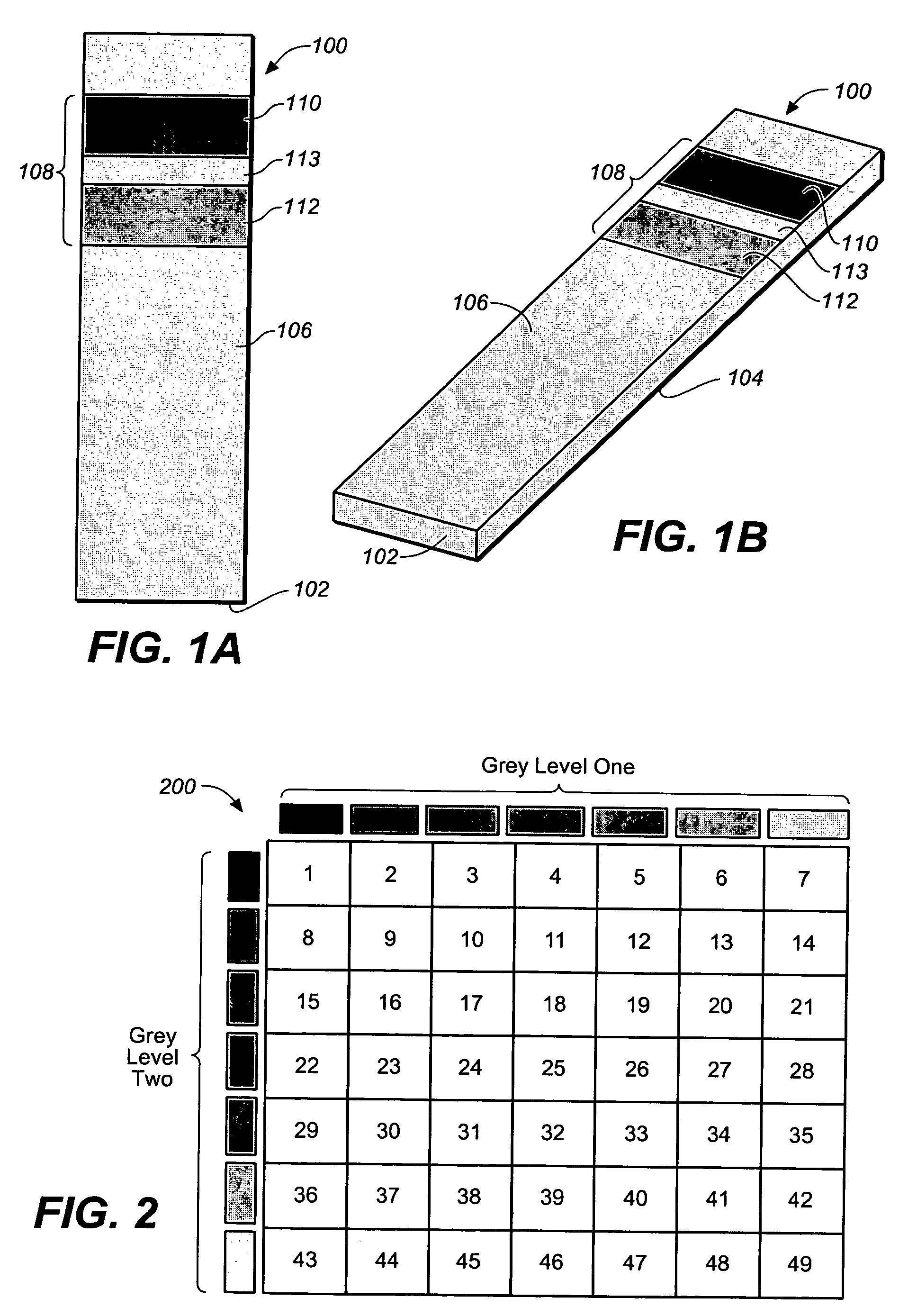
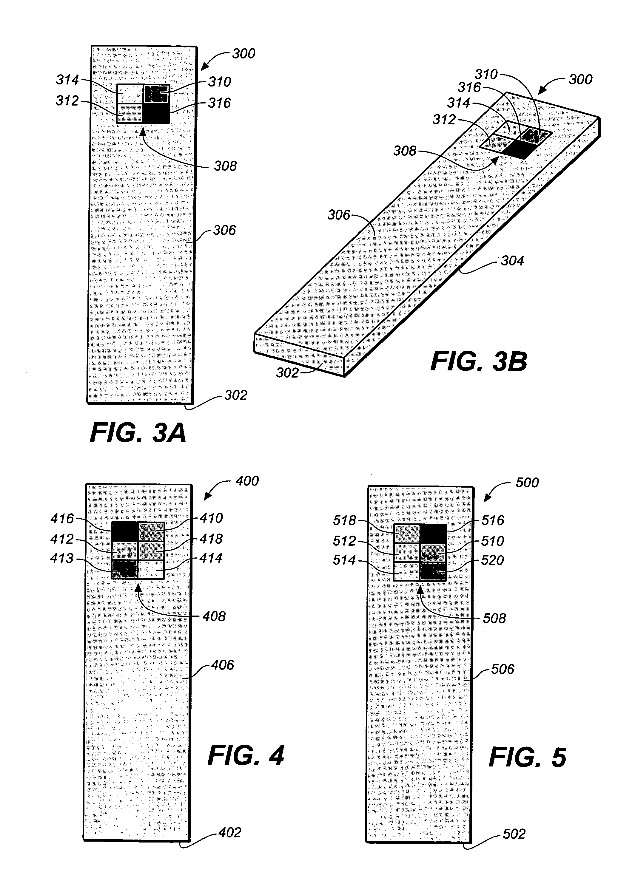
[0019]FIGS. 1A and 1B are simplified bottom and perspective views respectively of a test strip 100 for the determination of an analyte (such as glucose) in a body fluid sample (e.g. a whole blood sample) according to an exemplary embodiment of the present invention.
[0020]Test strip 100 includes a substrate 102 with a working surface 104 (not visible in the perspective of FIGS. 1A and 1B) for receiving the body fluid sample and a reverse surface 106 in opposition to working surface 104.
[0021]Test strip 100 also includes a permutative grey scale calibration pattern 108 disposed on reverse surface 106. In the embodiment of FIGS. 1A and 1B, the permutative grey scale calibration pattern 108 includes a first grey scale region 110 and a second grey scale region 112, with the first and second grey scale regions 110 and 112, respectively, being spaced apart by gap 113. However, once apprised of the present disclosure, one skilled in the art will recognize that grey scale calibration pattern...
PUM
Property
Measurement
Unit
electrochemical test
aaaaa
aaaaa
electrochemical
aaaaa
aaaaa
time
aaaaa
aaaaa
Abstract
A method for determining a test strip calibration code for use in a meter includes inserting a test strip into the meter. The inserted test strip having a substrate with a working surface for receiving the body fluid sample and a reverse surface that is in opposition to the working surface. The test strip also includes a permutative grey scale calibration pattern disposed on either of the working and reverse surfaces, with the permutative grey scale calibration pattern including more than one grey scale region. Moreover, the scale regions of the test strip define a grey scale permutation that uniquely corresponds to a calibration code of the test strip. The method also includes detecting the permutative grey scale calibration pattern with a grey scale photodetector module of the meter and determining a calibration code that uniquely corresponds to a grey scale permutation defined by the permutative grey scale calibration pattern based on permutation matrix stored in the meter.
Description
BACKGROUND OF THE INVENTION[0001]1. Field of the Invention[0002]The present invention relates, in general, to medical devices and, in particular, to methods, systems, test strips, and calibration strips used for the determination of analytes.[0003]2. Description of the Related Art[0004]A variety of systems for determining an analyte (e.g., glucose) in a body fluid sample (for example, a whole blood, plasma or interstitial fluid sample) are known and documented. These systems typically include a meter, at least one test strip, either electrochemical or photometric in nature, and at least one lancet. The lancet can, if desired, be integrated with the test strip. An example of such a system is the OneTouch® Ultra from Lifescan Inc., Milpitas, USA. Further representative systems, meters and test strips are described in, for example, U.S. Pat. Nos. 6,168,957B1; 5,708,247; 6,045,567 and 6,733,655, and US Patent Application Publication Nos. 2004 / 015102A and 2003 / 0207441A1, each of which is...
Claims
Application Information
Patent Timeline
Application Date:The date an application was filed.
Publication Date:The date a patent or application was officially published.
First Publication Date:The earliest publication date of a patent with the same application number.
Issue Date:Publication date of the patent grant document.
PCT Entry Date:The Entry date of PCT National Phase.
Estimated Expiry Date:The statutory expiry date of a patent right according to the Patent Law, and it is the longest term of protection that the patent right can achieve without the termination of the patent right due to other reasons(Term extension factor has been taken into account ).
Invalid Date:Actual expiry date is based on effective date or publication date of legal transaction data of invalid patent.

