
FEXT determination system

Active Publication Date: 2009-09-22
ASSIA SPE LLC CO THE CORP TRUST CO
View PDF34 Cites 23 Cited by
  • Summary
  • Abstract
  • Description
  • Claims
  • Application Information

AI Technical Summary

Benefits of technology

"The present invention provides methods, apparatus, computer program products, and other embodiments for determining interference between lines in a communication system, such as a DSL system. The interference is calculated using data that is readily available at the upstream end of the lines. The invention also provides crosstalk information to various components of the communication system, including systems compliant with DSM standards. The invention uses a decibel-magnitude representation of the interference, called Xlog(u,n), which is defined as the ratio of a line's source power into a matched load of 100 Ohms when no binder is present to the power at the output of the line when it is excited with the same source and the binder is present. The invention can be used in jointly determining spectra, even when no crosstalk cancellation is used in a given system. Overall, the invention provides a more accurate and efficient way to measure interference between lines in communication systems."

Problems solved by technology

Unreasonable static limits on and practices in DSL operation have frustrated efforts to improve service to users and to increase profitability and ubiquity for operators.
There also are probabilities of certain line lengths, presence of bridged taps, impulse noise, radio noise and other impairments.

Method used


Image

  • FEXT determination system
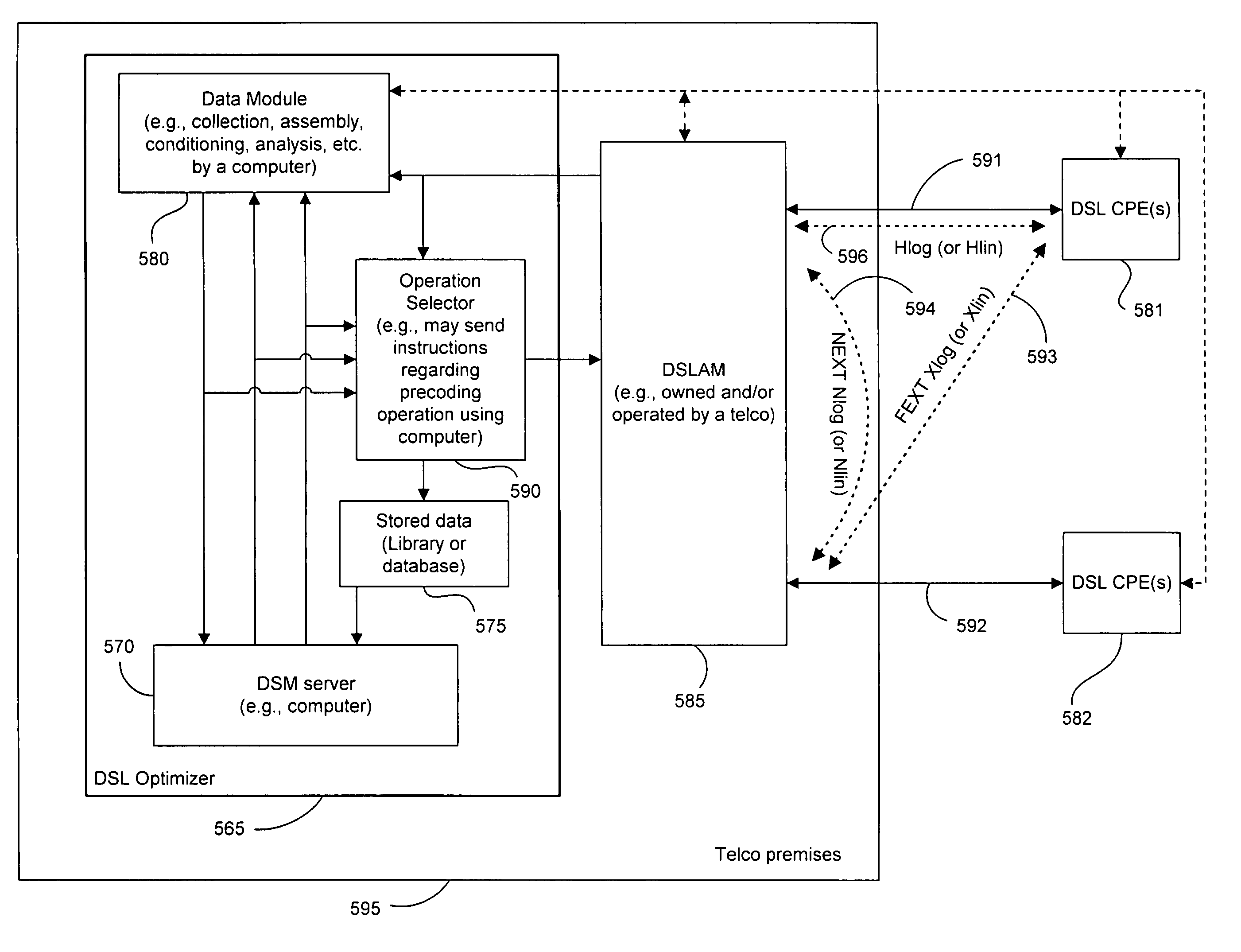
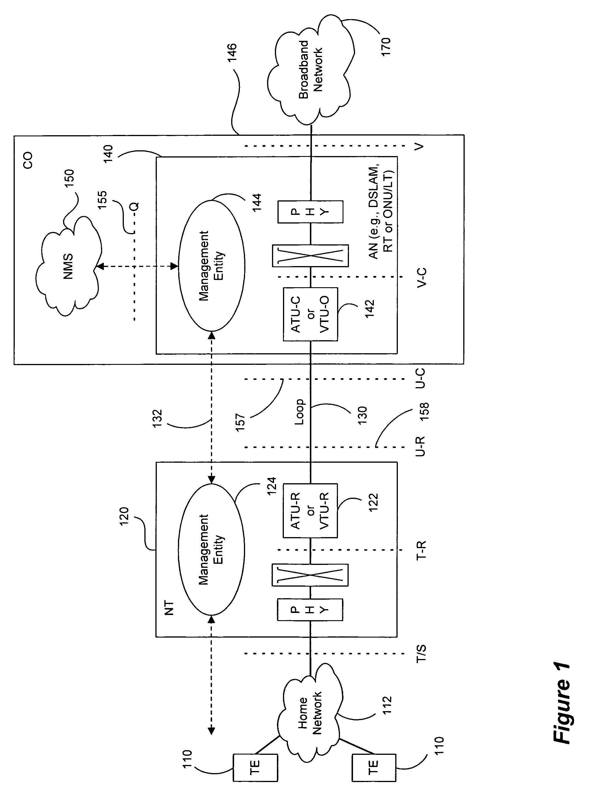
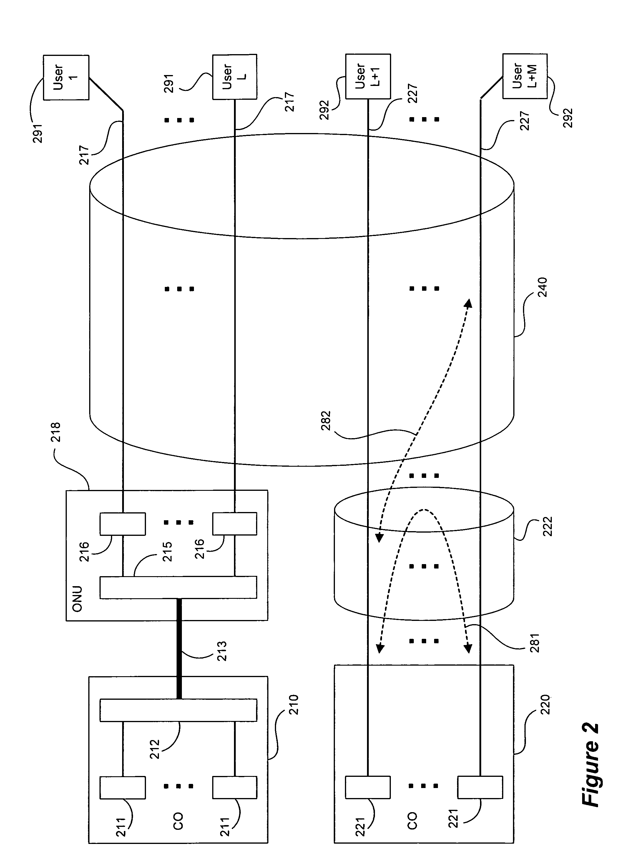
  • FEXT determination system
  • FEXT determination system

Examples


Embodiment Construction

[0023]The following detailed description of the invention will refer to one or more embodiments of the invention, but is not limited to such embodiments. Rather, the detailed description is intended only to be illustrative. Those skilled in the art will readily appreciate that the detailed description given herein with respect to the Figures is provided for explanatory purposes as the invention extends beyond these limited embodiments.

[0024]Embodiments of the present invention utilize data that is readily available at the upstream end of a pair of DSL loops to determine the FEXT interference induced by one line into the other DSL line. The FEXT interference is calculated using the NEXT interference that can be measured between the two lines at the upstream ends of the loops and the downstream channel transfer function of one of the lines. Because the NEXT and transfer function constitute a linear time-invariant system, as does the FEXT interference between the lines, the NEXT interf...


PUM


Abstract

Operational data is utilized to determine the FEXT interference induced by one line into the other DSL line. FEXT interference can be calculated using the NEXT interference measured between the two lines at the upstream ends of the loops and the downstream channel transfer function of one of the loops. Because the NEXT and transfer function constitute a linear time-invariant system, as does the FEXT interference between the lines, the NEXT interference and line transfer function can be multiplied (if in linear format) or added (if in logarithmic format) to approximate the FEXT interference between the lines. The collection of data, calculations and other functions performed in these techniques may be performed by a system controller, such as a DSL optimizer. An Xlog(u,n) quantity is a decibel-magnitude representation of the insertion-loss equivalent of FEXT transfer functions and is defined as the ratio of (1) a line u's source power into a matched load of 100 Ohms when no binder is present to (2) the power at the output of the subject line when line u is excited with the same source and the binder is present. Xlin(u,n) is the linear equivalent of Xlog(u,n). The Xlog(u,n) and Xlin(u,n) quantities may be represented in specific formats that assist in their use in DSL and other systems. When defined as a line's insertion loss, Xlin (or equivalently Xlog) does not include the effect of any transmit filter.

Description

CROSS-REFERENCE TO RELATED APPLICATIONS[0001]This application claims the benefit of priority under 35 U.S.C. § 119(e) of U.S. Provisional No. 60 / 572,051 filed on May 18, 2004, entitled DYNAMIC MANAGEMENT OF COMMUNICATION SYSTEM, the disclosure of which is incorporated herein by reference.STATEMENT REGARDING FEDERALLY SPONSORED RESEARCH OR DEVELOPMENT[0002]Not applicable.REFERENCE TO SEQUENCE LISTING, A TABLE, OR A COMPUTER PROGRAM LISTING COMPACT DISK APPENDIX[0003]Not applicable.BACKGROUND[0004]1. Technical Field[0005]This invention relates generally to methods, systems and apparatus for managing digital communication systems. More specifically, this invention relates to collecting operational data from modems and / or other components in a communication system, such as a DSL system or the like, and determining FEXT interference (far-end crosstalk) between two DSL lines without requiring direct measurement of the interference. Even more specifically, at least one embodiment of this i...

Claims


Application Information

Patent Timeline
Patent Type & Authority Patents(United States)
IPC IPC(8): H04B1/00H03K11/00H04B3/32H04L12/28H04L27/26H04M11/06
CPCH04B3/32
Inventor CIOFFI, JOHN M.
Owner ASSIA SPE LLC CO THE CORP TRUST CO
Learn More