
Method of determining the angular position of a headlight by several magnetic field measurement means

a technology of magnetic field and headlight, which is applied in the direction of instruments, galvano-magnetic hall-effect devices, electric devices, etc., can solve the problems of nuisance or dazzling, unwanted movement of headlights, and impairing the availability of headlights

Active Publication Date: 2009-09-29
VALEO VISION SA
View PDF11 Cites 21 Cited by
  • Summary
  • Abstract
  • Description
  • Claims
  • Application Information

AI Technical Summary

Benefits of technology

[0018]To resolve these problems, one embodiment of the invention proposes a method comprising a measurement step during which an intensity of a local magnetic field is measured in projection on at least a second measurement axis orthogonal to the first measurement axis by means of at least second measurement means that emit a second electrical measurement signal representing the intensity of the local magnetic field along the second measurement axis, and in that, during the second processing step, the electronic processor unit calculates a value representing an angle of a local magnetic field with respect to the first measurement axis in projection on the plane defined by the two measurement axes.

Problems solved by technology

However, traveling over the whole of the travel of the stepping actuator in order to obtain the reference angular position of the headlight causes an unwanted movement of the headlight.
This unwanted movement of the headlight may cause a nuisance or dazzling for a motorist traveling in the opposite direction.
Moreover, the unwanted movement of the headlight routinely impairs the availability of the headlight.
However, such a copying sensor is very expensive and complex to manufacture and calibrate.
In addition, the sensitivity of this type of sensor is not sufficient to precisely determine the instantaneous angular position of the headlight in end ranges of the range of movement of the headlight.
In addition, when this type of measurement device comprises a Hall effect sensor, the measurements made by the sensor are liable to be influenced by external constraints such as temperature or vibrations.

Method used


Image

  • Method of determining the angular position of a headlight by several magnetic field measurement means
  • Method of determining the angular position of a headlight by several magnetic field measurement means
  • Method of determining the angular position of a headlight by several magnetic field measurement means

Examples


Embodiment Construction

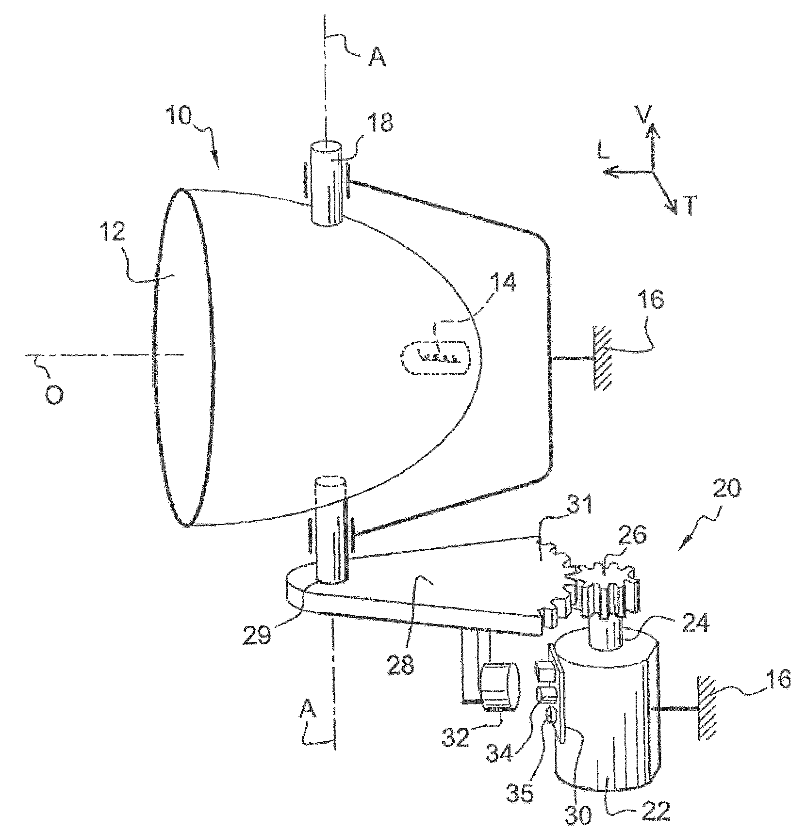
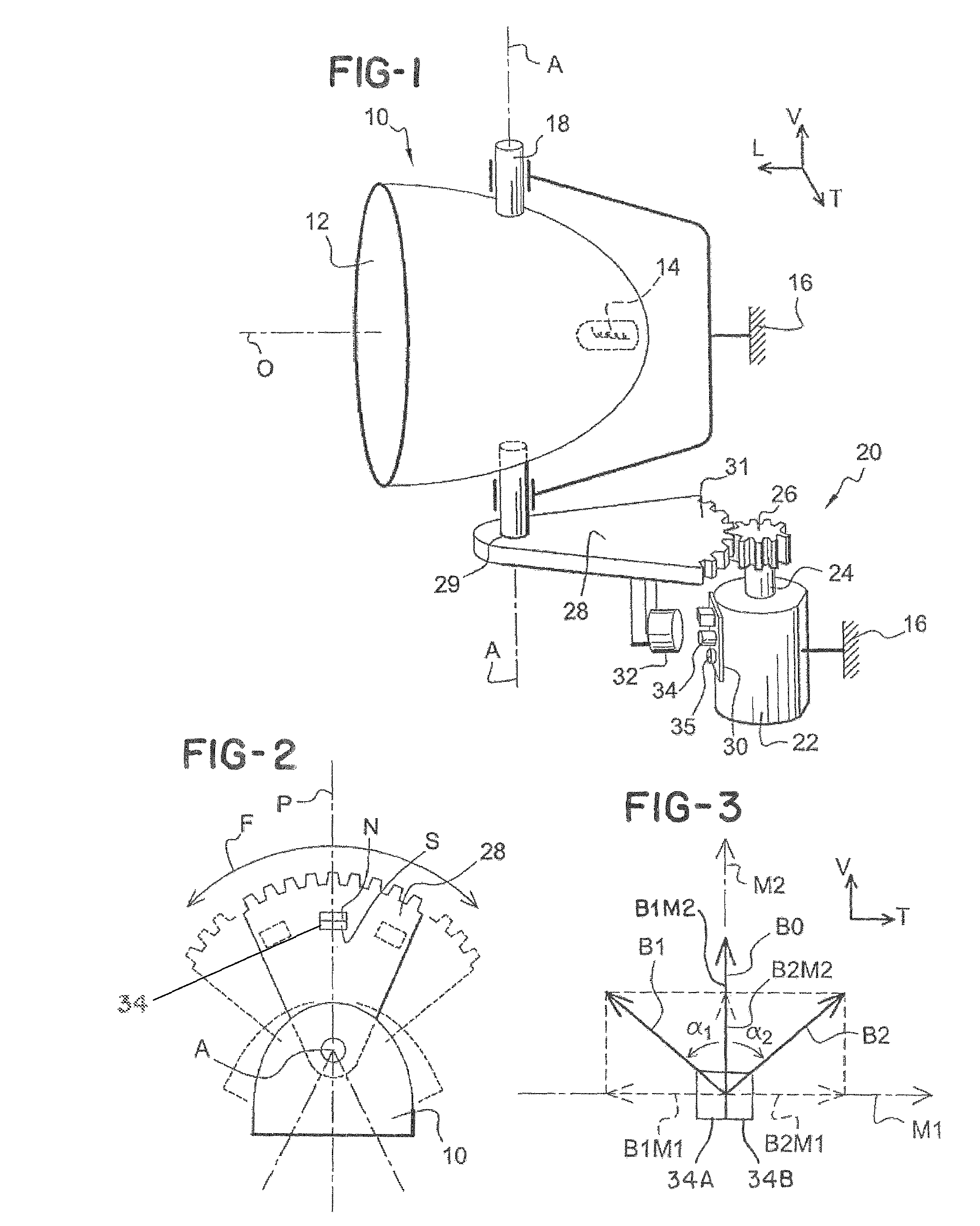
[0044]For the remainder of the description, there will be adopted, non-limitingly, a longitudinal, vertical and transverse orientation that is fixed with respect to the body of the motor vehicle and that is indicated by the trihedron L, V, T in FIG. 1.

[0045]Subsequently, identical, analogous or similar elements will be designated by the same reference numbers.

[0046]FIG. 1 depicts a motor vehicle headlight 10 that comprises here a reflector 12 inside which a lamp 14 is mounted. The headlight 10 is able to emit a light beam along an optical axis O of roughly longitudinal orientation.

[0047]The headlight 10 is mounted for rotation about a vertical axis A with respect to the body 16 of the motor vehicle. To this end, the headlight 10 comprises two bottom and top swivels 18 of axis A.

[0048]The headlight 10 is thus able to be oriented according to several angular positions about the axis A in a range of movement that is delimited by two extreme angular positions. For the remainder of the d...


PUM


Abstract

A measurement device and method for determining the angular position of a pivoting headlight by means of a measurement device that comprises at least one ferromagnetic element that emits a local magnetic field, first means of measuring the local magnetic field in projection on a first axis, the at least one ferromagnetic element being mounted so as to pivot with respect to the at least one first measurement means, and an electronic processing unit, the method comprising a measurement step, and a second processing step during which the electronic processing unit calculates the angular position of the headlight, that, during the measurement step, the intensity of the local magnetic field is measured in projection on a second axis orthogonal to a first axis, and that, during a second processing step, the electronic processing unit calculates a value representing the angle of the local magnetic field with respect to the first axis.

Description

CROSS-REFERENCE TO RELATED APPLICATIONS[0001]This application claims priority to French Application No. 0603221 filed Apr. 12, 2006, which application is incorporated herein by reference and made a part hereof.BACKGROUND OF THE INVENTION[0002]1. Field of the Invention[0003]The invention concerns a method of determining the instantaneous angular position of a headlight, in particular for a motor vehicle, that is mounted so as to pivot about a rotation axis in a predetermined range of movement.[0004]2. Description of the Related Art[0005]Some motor vehicles are in fact equipped with front headlights that are mounted so as to rotate about a vertical axis. Such a headlight makes it possible, for example when a vehicle is approaching a bend, to illuminate the portion of roadway that is situated in the curvature of the bend.[0006]The invention is also applicable to headlights that are mounted so as to rotate about a transverse axis so as to correct the elevation of the headlight according...

Claims


Application Information

Patent Timeline
Patent Type & Authority Patents(United States)
IPC IPC(8): G01B7/30
CPCB60Q1/076G01D3/028G01D5/145
Inventor FLANDRE, LOÏCLETOUMELIN, RÉMYUHRICH, ARNAUD
Owner VALEO VISION SA
Learn More