
Three-dimensional forming display system

a display system and three-dimensional technology, applied in the field of three-dimensional diorama display systems, can solve the problems of system not becoming popular and/or saleable, complex systems, and prior art products generally failing to provide the desired interest generation, etc., to achieve rapid and easy assembly, reduce storage space, and quickly and easily fully erected

Inactive Publication Date: 2009-10-06
CROWELL CHRISTOPHER S +1
View PDF5 Cites 20 Cited by
  • Summary
  • Abstract
  • Description
  • Claims
  • Application Information

AI Technical Summary

Benefits of technology

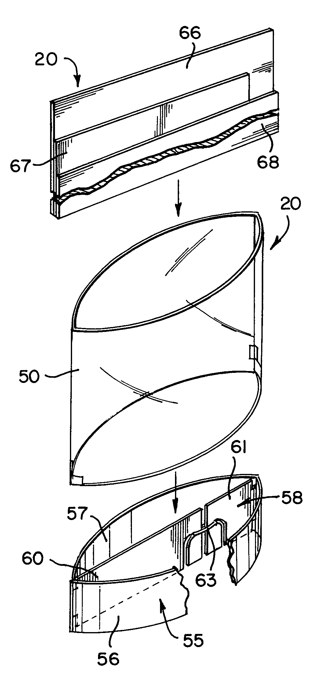
[0013]By employing the present invention, all of the difficulties and inabilities of the prior art are eliminated and a unique, visually exciting and interest generating three-dimensional diorama display system is attained. These desirable results are achieved in the present invention by providing a unique, pre-formed holding member which is quickly and easily assembled into the three-dimensional diorama display. In addition, the holding member is shipped or stored in a substantially flat configuration in order to reduce storage space. Furthermore, in accordance with the unique aspects of the present invention, the interest generating, three-dimensional / diorama display system of the present invention is quickly and easily fully erected from its flat, generally two-dimensional configuration into a three-dimensional diorama display, possessing all of the attributes desired by consumers.
[0014]In accordance with the present invention, a holding member is provided which is constructed for being quickly and easily converted from a two-dimensional, substantially flat configuration into a three-dimensional, fully erect, fully assembled, interest generating, visually exciting diorama displaying position which incorporates any photograph desired by the consumer to be displayed. Although prior art constructions exist for various diorama displays, the present invention provides a unique construction which achieves a quickly and easily constructed three-dimensional diorama display which enables the consumer to display any desired photograph in a unique, interest generating and visually exciting manner.
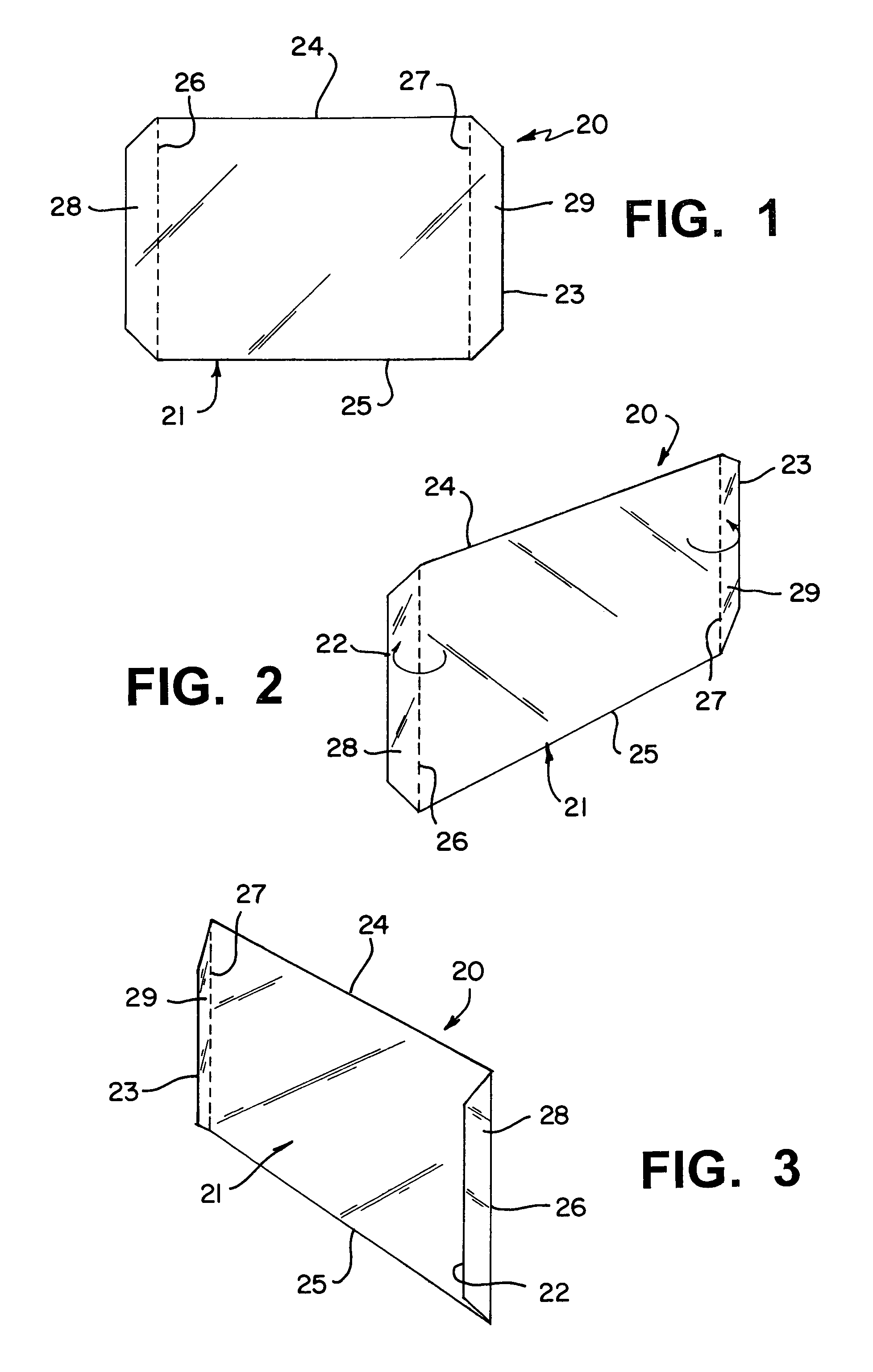
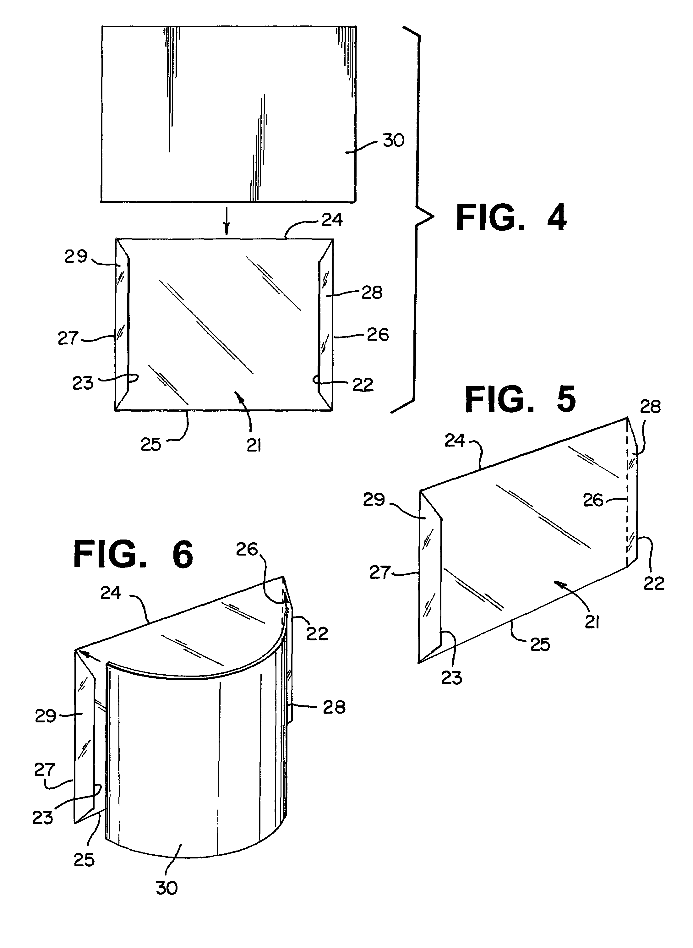
[0015]In accordance with the present invention, a substantially flat transparent sheet of material is constructed having a desired size and shape for receiving and holding a particular photograph construction or configuration. In addition, the transparent sheet of material incorporates cooperating pre-formed score lines formed along the opposed edges of the transparent sheet, effectively establishing flanges at the opposed side edges thereof. Whenever desired by the consumer, each of the flanges are arcuately pivoted along the associated score lines, thereby enabling the flanges to extend inwardly, towards each other, establishing two cooperating photograph edge holding flanges.

Problems solved by technology

However, in spite of the effort expended by many companies to satisfy consumer interests, these prior art products have generally failed to provide the desired interest generating results, in a reasonably priced consumer product.
Typically, these prior art products employ complex systems which produce three-dimensional displays when unfolded or erected.
However, in spite of some visually unique appearances being generated by such products, the overall cost of production and complexity of assembly for these systems have prevented the systems from becoming popular and / or saleable.
However, these prior art attempts have also failed to generate the interest being sought, largely due to an inability to achieve an easily erected and employable product.

Method used


Image

  • Three-dimensional forming display system
  • Three-dimensional forming display system
  • Three-dimensional forming display system

Examples


Embodiment Construction

[0039]By referring to FIGS. 1-29, along with the following detailed discussion, the construction and operation of several preferred alternate embodiments of the present invention can best be understood. In addition, further alternate embodiments or constructions can be implemented using the teaching of the present invention. Consequently, it is to be understood that the following detailed disclosure and the specific embodiments shown herein, are provided for exemplary purposes only and are not intended as a limitation of the present invention.

[0040]In FIGS. 1-3, picture or photograph holding, three-dimensional / diorama forming display system 20 is fully depicted. As shown, display system 20 comprises panel 21, which is formed from a substantially flat piece of transparent material and comprises side edges 22 and 23, top edge 24, and bottom edge 25. In addition, panel 21 incorporates score lines 26 and 27 which are formed in panel 21, spaced inwardly from side edges 22 and 23. As deta...


PUM


Abstract

By providing a unique, pre-formed holding member which is quickly and easily assembled into the three-dimensional diorama display, a unique, visually exciting and interest generating three-dimensional diorama display system is attained. In the preferred embodiment of the present invention, a substantially flat transparent sheet of material is constructed having a desired size and shape for receiving and holding a particular photograph construction or configuration. In addition, the transparent sheet of material incorporates cooperating pre-formed score lines formed along the opposed edges of the transparent sheet, effectively establishing flanges at the opposed side edges thereof. Each of the flanges are arcuately pivoted along the associated score lines, thereby enabling the flanges to extend inwardly, towards each other, establishing two cooperating photograph edge holding flanges.

Description

RELATED APPLICATIONS[0001]This application is a Continuation-in-Part application of U.S. Ser. No. 11 / 654,469 filed Jan. 17, 2007 entitled THREE DIMENSIONAL DIORAMA DISPLAY SYSTEM which is related to U.S. Provisional Patent Application Ser. No. 60 / 764,296 filed Feb. 1, 2006 entitled THREE DIMENSIONAL DIORAMA DISPLAY SYSTEM.TECHNICAL FIELD[0002]This invention relates to three-dimensional diorama display systems and, more particularly, to such products which enable the user to create a three dimensional diorama display system from a two-dimensional, substantially flat configuration.BACKGROUND ART[0003]With the ever increasing and widening interests of consumers and the variety of products which consumers wish to purchase, manufacturers have sought to provide competitive products which will satisfy consumers' interests and desires. In this regard, inexpensive or reasonably priced display systems have long been an area of interest for consumers, particularly those display systems which p...

Claims


Application Information

Patent Timeline
Patent Type & Authority Patents(United States)
IPC IPC(8): G09F1/00
CPCG09F1/06
Inventor CROWELL, CHRISTOPHER S.KLIM, JOSEPH R.
Owner CROWELL CHRISTOPHER S
Learn More