Fuel deposit testing using burner-based exhaust flow simulation system

a simulation system and engine technology, applied in the direction of instruments, structural/machine measurement, chemical methods analysis, etc., can solve the problems of inconvenient separate evaluation of individual variables, high maintenance costs, and inconsistent use of real engines for long-term testing,

Active Publication Date: 2009-10-06
SOUTHWEST RES INST
View PDF22 Cites 9 Cited by
  • Summary
  • Abstract
  • Description
  • Claims
  • Application Information

AI Technical Summary

Problems solved by technology

However, the use of a real engine for long term testing can be inconsistent, maintenance intensive, and expensive to operate.
In addition, a real engine does not conveniently permit the separate evaluation of individual variables, such as the effects of various constituents of fuel and oil.

Method used


Image

  • Fuel deposit testing using burner-based exhaust flow simulation system
  • Fuel deposit testing using burner-based exhaust flow simulation system
  • Fuel deposit testing using burner-based exhaust flow simulation system

Examples


Embodiment Construction

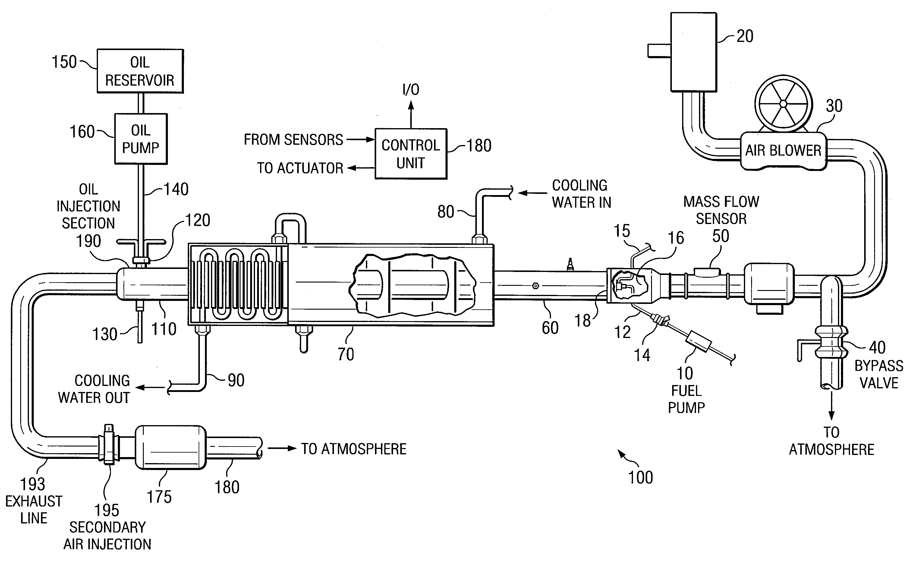
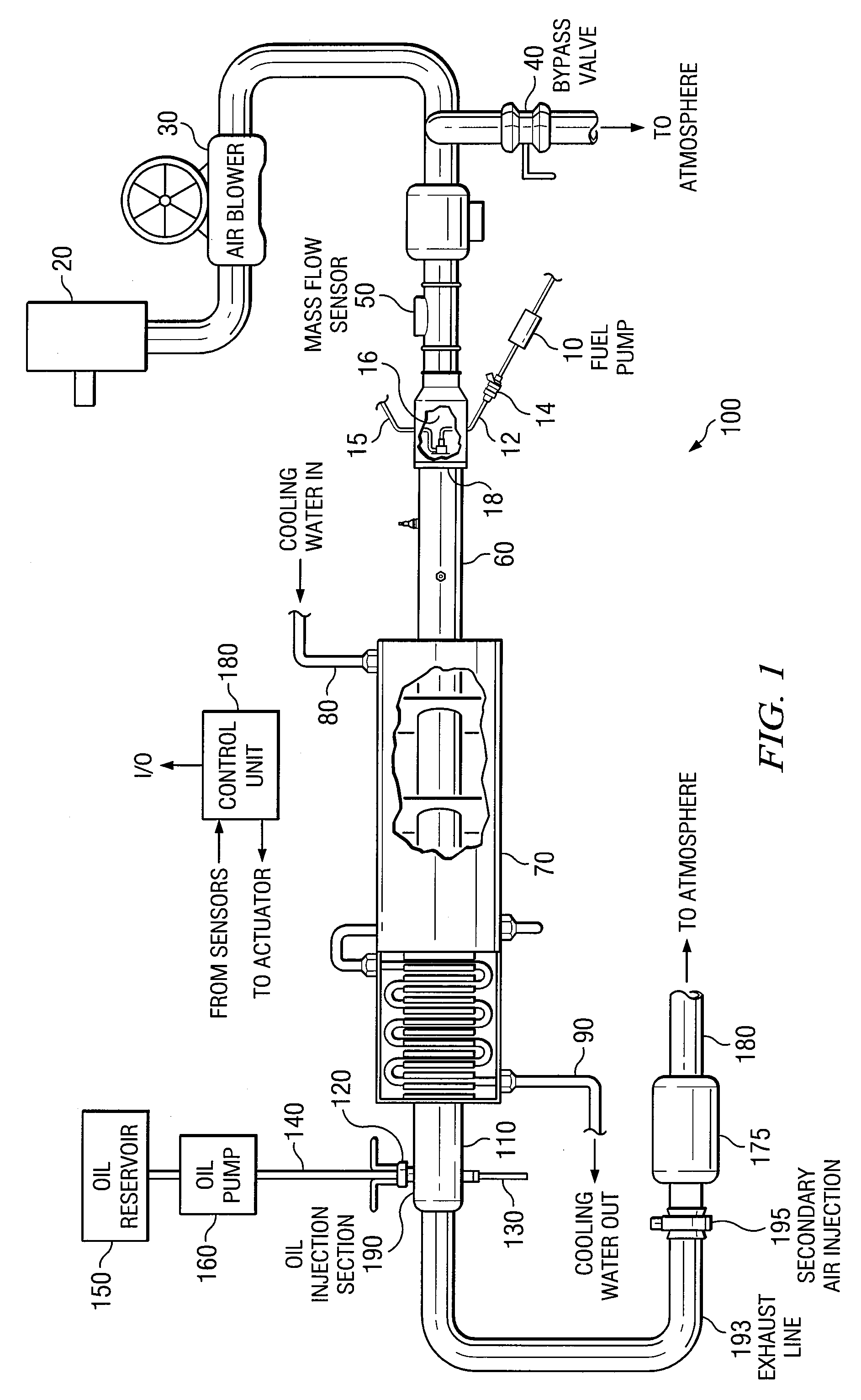
[0009]The following description is directed to a burner-based exhaust flow simulation system, which produces a flow of exhaust gas with a composition and temperature corresponding to those produced by the internal combustion engine of a motor vehicle. The system can be used with or without introducing oil to simulate engine oil consumption.

[0010]As an example of one application of an exhaust flow simulation system, an emissions control device can be installed on the exhaust line of the system. The effect of extended driving conditions and elevated temperatures on the emissions control device can be simulated. The system can also produce the effects of additives and contaminants from the engine fuel and lubricant oil on the durability of the emissions control device. The system is capable of “aging” the device, which can then be evaluated, and if desired, performance-tested on an actual vehicle.

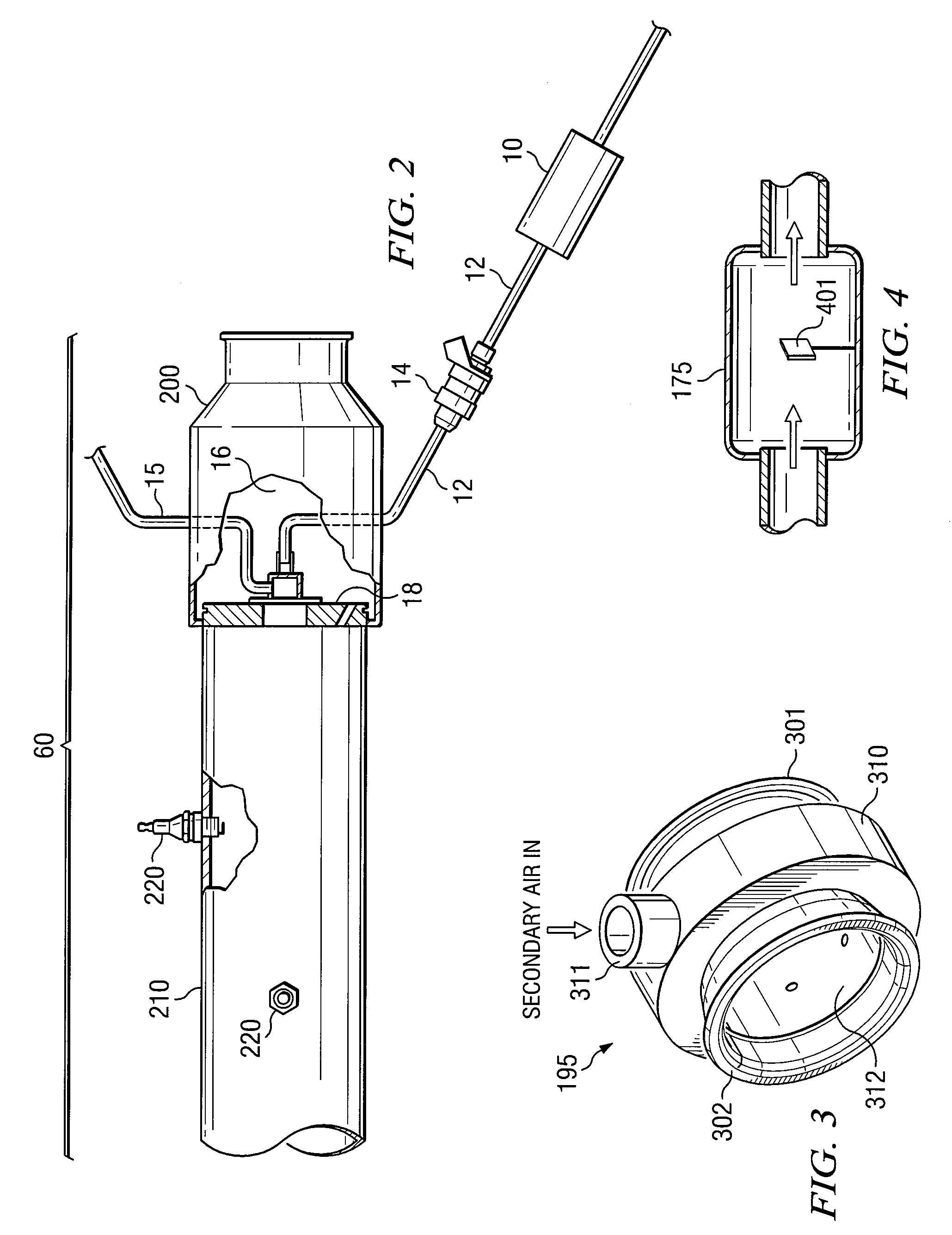
[0011]Other applications of the exhaust flow simulation system are possible. Various senso...


PUM

PropertyMeasurementUnit
inner diameteraaaaaaaaaa
diameteraaaaaaaaaa
temperatureaaaaaaaaaa

Abstract

A method of using an exhaust flow simulation system to test the effects of exhaust system conditions on various materials. A typical exhaust flow simulator is a burner-based system, in which exhaust from burner combustion is exhausted through an exhaust line. A “test coupon” of the material may be placed at an appropriate location in the flow line, and tested to determine how it is affected by the exhaust resulting from various fuels and additives.

Description

RELATED PATENT APPLICATION[0001]This application claims the benefit of U.S. Provisional Application No. 60 / 734,024, filed Nov. 4, 2005 and entitled “Fuel Deposit Testing Using Burner Based Exhaust Flow Simulation System.”TECHNICAL FIELD OF THE INVENTION[0002]The present application relates in general to systems for simulating the exhaust flow of an engine over extended driving conditions and high temperatures.BACKGROUND OF THE INVENTION[0003]As a result of stricter regulations for automotive emissions, it was desired to design a testing apparatus and procedure for testing emissions control devices. Historically, an actual internal combustion engine was used for such evaluations. However, the use of a real engine for long term testing can be inconsistent, maintenance intensive, and expensive to operate. In addition, a real engine does not conveniently permit the separate evaluation of individual variables, such as the effects of various constituents of fuel and oil.[0004]U.S. Patent ...

Claims


Application Information

Patent Timeline
Patent Type & Authority Patents(United States)
IPC IPC(8): G01N17/00G01N25/00G01N31/12
CPCG01N17/00G01N17/043Y10T436/100833
Inventor TIMMONS, SUZANNE A.TIMMONS, SCOTT F.
Owner SOUTHWEST RES INST
Why Eureka
Try Eureka