Conducting member and connector having conducting member
a technology of conducting member and connector, which is applied in the direction of connection contact member material, securing/insulating coupling contact member, coupling device connection, etc., can solve the problems of increasing the number of components, time and labor required for assembling the connector, and the difficulty of achieving a compact design of the connector, so as to reduce the number of components and compact the effect of size and compactness
- Summary
- Abstract
- Description
- Claims
- Application Information
AI Technical Summary
Benefits of technology
Problems solved by technology
Method used
Image
Examples
first embodiment
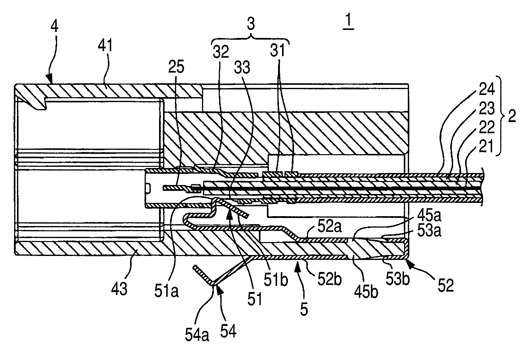
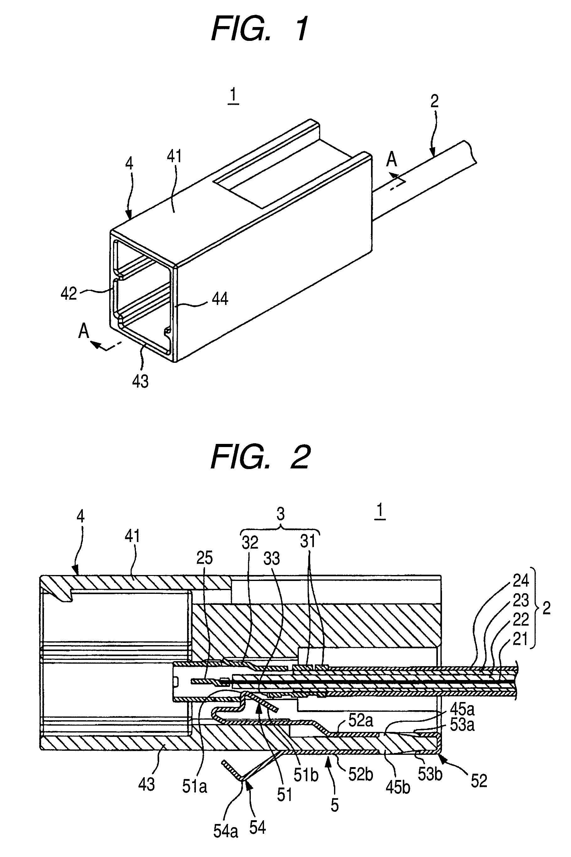
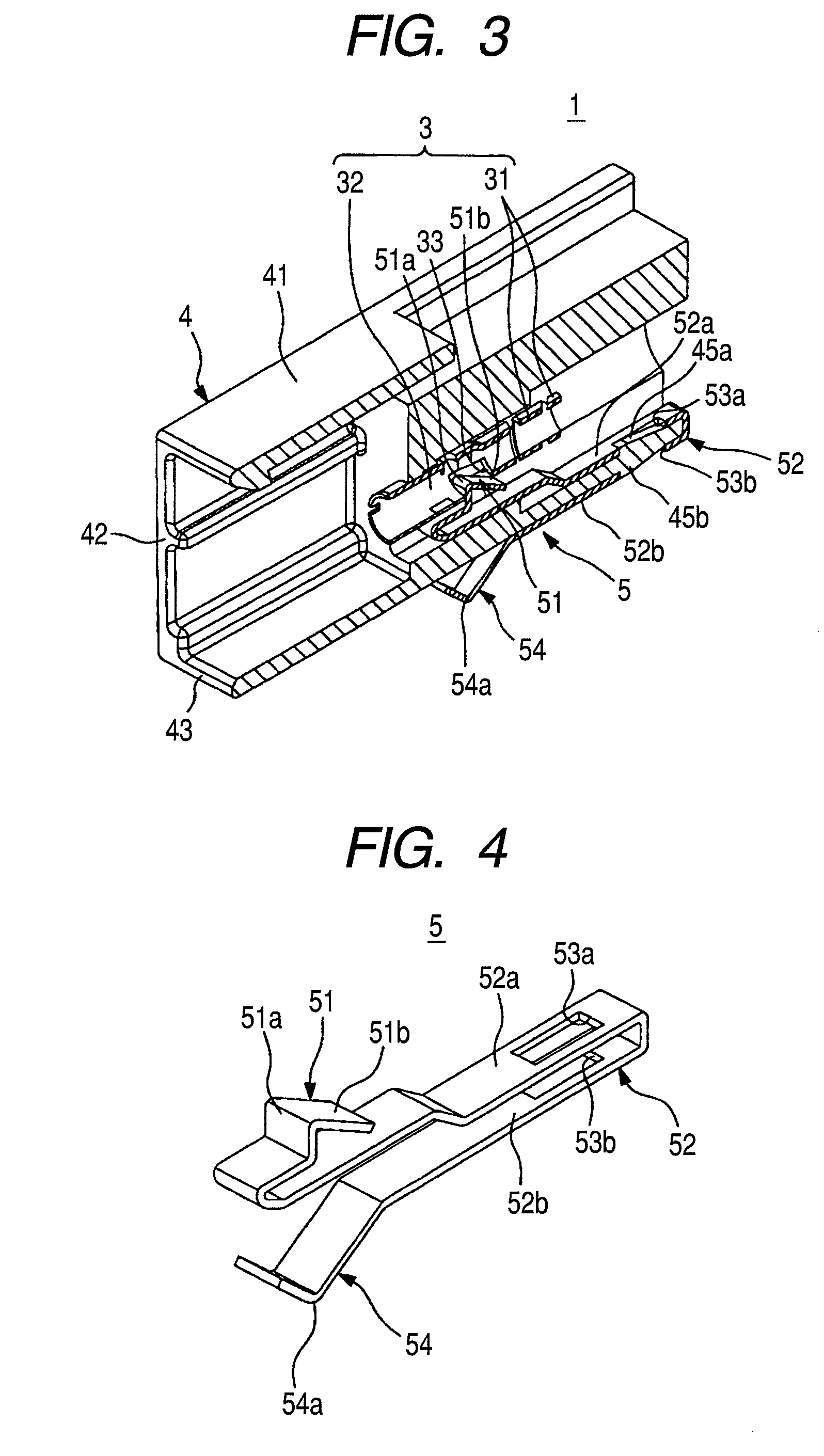
[0030]A first embodiment of a connector of the present invention will now be described with reference to FIGS. 1 to 4. FIG. 1 is a perspective view showing the connector of the first embodiment. FIG. 2 is a cross-sectional view taken along the line A-A of FIG. 1. FIG. 3 is a cross-sectional, perspective view taken along the line A-A of FIG. 1. In FIG. 3, the showing of a wire (cable) and an inner terminal connected to a core wire of the wire is omitted. FIG. 4 is a perspective view showing a conducting member of the connector of FIG. 2.
[0031]The connector 1 shown in FIGS. 1 to 3 is for use with a wire harness for installation on an automobile or the like, and this connector 1 comprises a ground terminal 3 (corresponding to a terminal in the claimed invention) connected to an end portion of the coaxial cable 2 (corresponding to a wire in the claimed invention), a synthetic resin-made housing 4 receiving the ground terminal 3 therein, and an earth plate 5 (corresponding to a conductin...
second embodiment
[0051]Next, a second embodiment of a connector of the invention will be described with reference to FIGS. 5 to 8. FIG. 5 is a cross-sectional, perspective view showing the connector of this second embodiment. In FIG. 5, the showing of a wire (cable) and an inner terminal connected to a core wire of the wire is omitted. FIG. 6 is a perspective view of a conducting member of the connector of FIG. 5. FIG. 7 is a perspective view showing a condition in which the conducting member and a terminal of the connector of FIG. 5 are connected together. FIG. 8 is a plan view showing the condition in which the conducting member and the terminal of the connector of FIG. 5 are connected together. In FIGS. 5 to 8, those portions identical in construction to those of the above first embodiment will be designated by identical reference numerals, respectively, and detailed description thereof will be omitted.
[0052]As shown in FIG. 5, the connector 101 of this embodiment comprises the ground terminal 3,...
PUM
 Abstract
Description
Claims
Application Information
 - R&D
- Intellectual Property
- Life Sciences
- Materials
- Tech Scout
- Unparalleled Data Quality
- Higher Quality Content
- 60% Fewer Hallucinations
Browse by: Latest US Patents, China's latest patents, Technical Efficacy Thesaurus, Application Domain, Technology Topic, Popular Technical Reports.
© 2025 PatSnap. All rights reserved.Legal|Privacy policy|Modern Slavery Act Transparency Statement|Sitemap|About US| Contact US: help@patsnap.com


