Snap-in disk and overload clutch with a snap-in disk

a technology of snap-in disks and overload couplings, which is applied in the direction of slip couplings, couplings, mechanical devices, etc., can solve the problems of cost-intensive and labor-intensive manufacture of detent disks that are common today, and achieve the effect of convenient and reliabl

Active Publication Date: 2009-10-06
ROBERT BOSCH GMBH
View PDF11 Cites 0 Cited by
  • Summary
  • Abstract
  • Description
  • Claims
  • Application Information

AI Technical Summary

Benefits of technology

[0005]Detent disks which are common today are cost-intensive and laborious to manufacture. They are created either by using a material-removing process on solid material or by machining a semi-finished product. Additional machining work is often required to create a rotary driving device, e.g., a hammer tube. In contrast, the proposed detent disk can be manufactured easily using powder metallurgy, e.g., as sintered compact, or using an injection-moulding method, e.g., an MIM (metal injection moulding) process. The shape and geometry of the detent disk are reproducibly defined in the manufacturing process using a mould. As such, there exists a great deal of freedom in terms of shape. Uniform material wall thicknesses can be attained, even when the geometry is complex, and a compact, solid component can be created. The detent disk advantageously has an outer diameter with a contour that can vary in terms of shape. This makes it possible to increase durability while keeping the material wall thickness the same. The material wall thickness can be reduced for a given durability, which results in a savings of weight, material usage and costs.
[0015]With one method, it is proposed that the detent disk be formed using a mould-based, powder metallurgical method. Preferably, the detent disk can be formed by a sintered detent disk body or by a detent disk body manufactured using an injection-moulding method. Shaping by using a material-removing process on solid material or machining a semi-finished product can be eliminated.

Problems solved by technology

Detent disks which are common today are cost-intensive and laborious to manufacture.

Method used


Image

  • Snap-in disk and overload clutch with a snap-in disk
  • Snap-in disk and overload clutch with a snap-in disk
  • Snap-in disk and overload clutch with a snap-in disk

Examples


Embodiment Construction

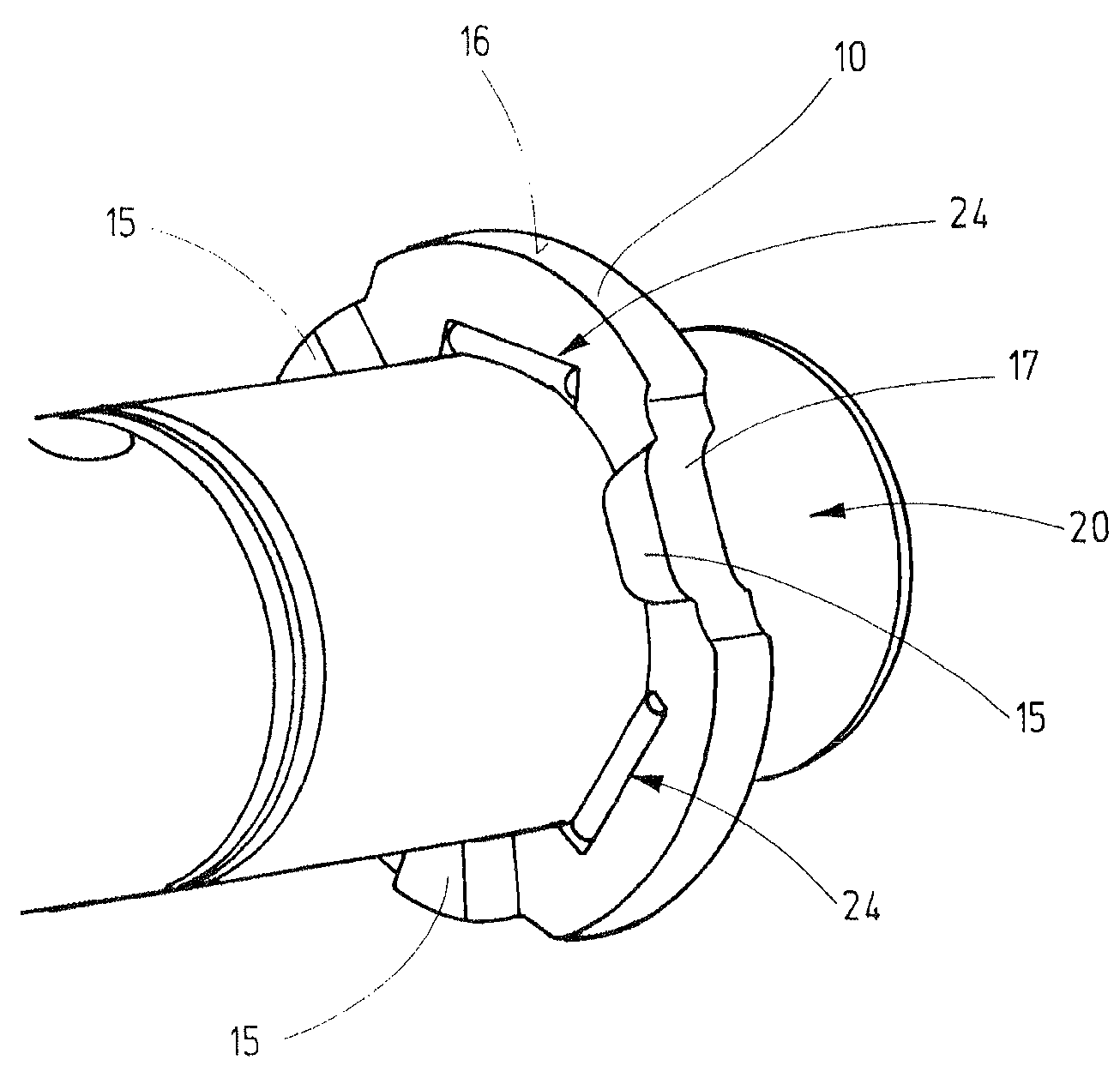
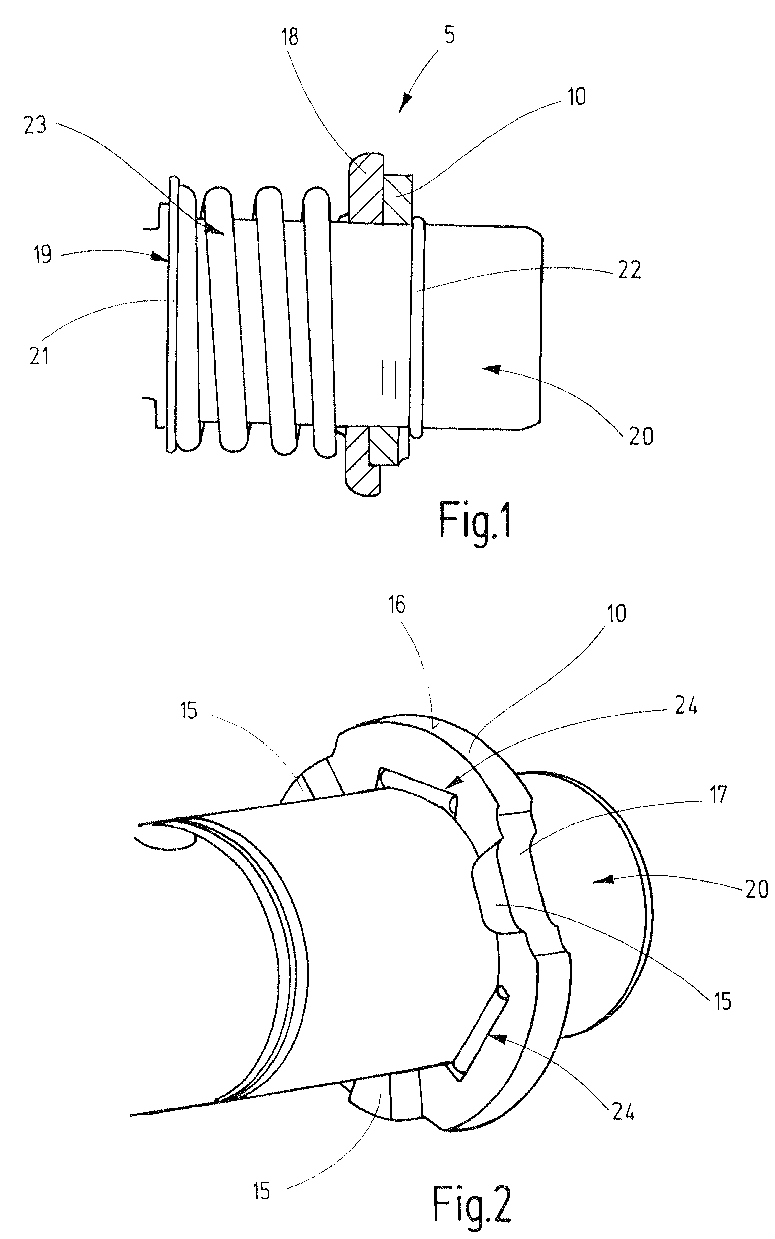
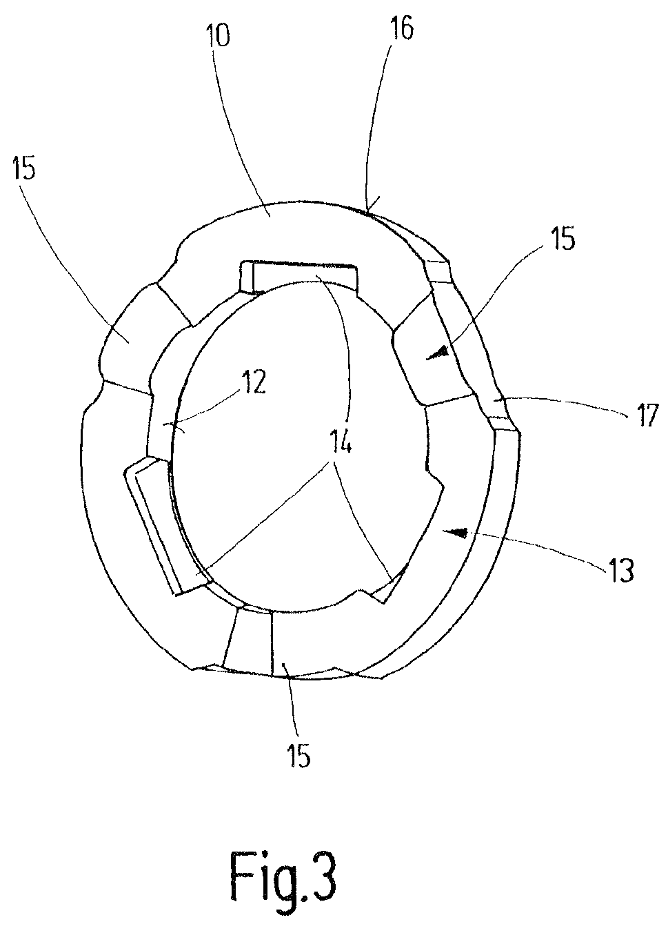
[0022]FIGS. 1 through 3 show various views of a preferred detent disk 10 in the installed state, and the details of a preferred overload coupling according to the present invention.

[0023]The side view in FIG. 1 shows a section of a preferred rotary hammer with a rotary and / or percussive drive 20, configured as a hammer tube, in the region of its overload coupling, shown in a sectional view. A compression spring 23, a spur gear 18, and detent disk 10 are located on hammer tube 20 and are supported across the diameter of hammer tube 20. Hammer tube 20 serves to induce rotational motion in a not-shown tool. Detent disk 10 is pressed by a compression spring 23 against a snap ring 22 and, therefore, against hammer tube 20. Compression spring 23 is pressed forward, in the direction of the tool (not shown), by a supporting ring 19 and a snap ring 21. As a result, an axial force is introduced into hammer tube 20.

[0024]Detent disk 10 is driven in a rotary manner with hammer tube 20 via tange...


PUM


Abstract

A detent disk for an overload coupling part has a detent disk body configured as a powder-metallurgy produced disk body, the detent disk body has a substantially uniform wall thickness and an inner circumference, and at least one driving device for driving in a rotary manner is provided on the inner circumference and configured as a driving pocket.

Description

CROSS REFERENCE TO A RELATED APPLICATION[0001]The invention described and claimed hereinbelow is also described in German Patent Application DE 10 2004 036 586.5 filed on Jul. 28, 2004. This German Patent Applications, whose subject matter is incorporated here by reference, provides the basis for a claim of priority of invention under 35 U.S.C. 119(a)-(d).BACKGROUND OF THE INVENTION[0002]The present invention relates to a detent disk and an overload coupling with a detent disk.[0003]Hand-guided machine tools such as rotary hammers and percussion hammers are usually equipped with an overload coupling that serves to protect an operator and the machine, and is designed to limit the maximum torque applied to the machine and to protect the drive from short-circuit operation or overload. This is brought about, e.g., by interrupting the rotary motion of the hammer tube, it being possible for torque to be transmitted by a spur gear transmission, the spur gear of which is connected by a sepa...

Claims


Application Information

Patent Timeline
Patent Type & Authority Patents(United States)
IPC IPC(8): F16D7/04
CPCF16D7/044
Inventor VEIT, JUERGENSAUR, DIETMARHEINZELMANN, HELMUT
Owner ROBERT BOSCH GMBH
Why Eureka
Try Eureka