Method for manufacturing a structure

a manufacturing method and structure technology, applied in the direction of manufacturing tools, ceramic shaping cores, synthetic resin layered products, etc., can solve the problems of insufficient bonding, high construction equipment or operation cost, and inability to bond compact components with each other in autoclaves, etc., to achieve excellent cost effectiveness and uniform pressure

Inactive Publication Date: 2006-05-30
SUBARU CORP
View PDF14 Cites 30 Cited by
  • Summary
  • Abstract
  • Description
  • Claims
  • Application Information

AI Technical Summary

Benefits of technology

[0031]A first object of the present invention is to provide a bonding method using spherical bodies made of silico

Problems solved by technology

Although the autoclave used in the process of manufacturing aircraft components was indeed effective in applying uniform pressure even to curved bonded surfaces of the components, the cost for constructing the equipment or the operation cost was high because the autoclave was large in scale and had a special structure.
Accordingly, the autoclave was not suitable for bonding compact components with each other or for bonding general-purpose components with each other because the cost increased too much.
When volume contraction occurred due to the hardening reaction of the bonding adhesive after then, the bonding adhesive in this pressurized portion might become thin so that sufficient bonding could not be obtained.
Thus, suitable magnitude of pressure could not be applied in accordance with the adherends or the kind of bonding adhesive.
Thus, the manufacturing cost thereof increased.
However, according to the method (1), as shown in FIGS. 28 and 29, complicated works were required.
In addition, when a large-sized structure such a sawing box portion of an aircraft was formed, a large number of rivets 540 were required to result in increase of the weight, contrary to the request of reduction in weight.
Further, the cost to manufacture the rivets 540 was required separately.
On the other hand, according to the method (2), the open portions of the box-like bodies had to be coupled by rivets so that there arose problems similar to those in the method (1).
That is, works were complicated, the weight of the structure increased, and the cost increased.
Accordingly, the work (demolding work) for extracting the metal mandrels from the insides of the box-like bodies was so difficult that the manufacturing cycle was delayed.
However, when the stiffened panel 610 was manufactured, the shapes of the bagging films were not stable, so that it was difficult to dispose the bagging films accurately to match the internal shapes of the hollow portions.
When the bagging films were not disposed accurately to match the internal shapes of the hollow portions, the pressure applied to the prep

Method used


Image

  • Method for manufacturing a structure
  • Method for manufacturing a structure
  • Method for manufacturing a structure

Examples


first embodiment

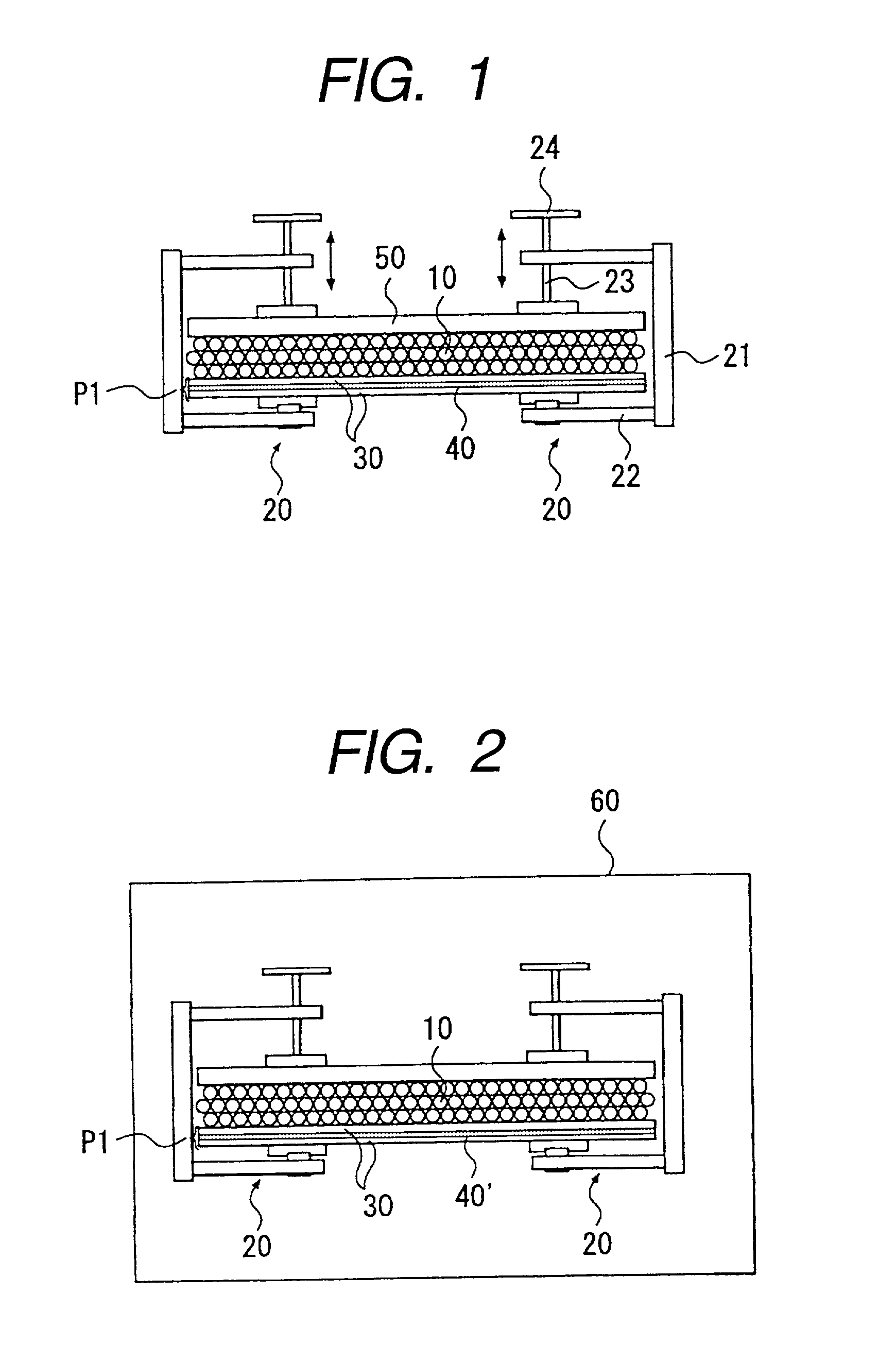
[0109]In this embodiment, with reference to FIG. 1, description will be made on a method for bonding two flat plates 30 as adherends by use of spherical bodies 10 made of silicon rubber and C-clamps 20.

[0110]First, surface treatment is carried out on bonded surfaces of the two flat plates 30. This surface treatment is carried out in order to eliminate inorganic matter such as rust or organic matter such as finger marks adhering to the respective bonded surfaces and impeding bonding. The surface treatment may be carried out in a mechanical method in which the respective bonded surfaces are polished and then degreased with a solvent; or in a chemical method in which chemicals are applied onto the bonded surfaces after degreasing with a solvent.

[0111]Next, a bonding adhesive 40 is applied onto the respective bonded surfaces of the two flat plates 30, and the bonded surfaces are laminated to each other (lamination step). In this embodiment, a room-temperature setting bonding adhesive su...

second embodiment

[0130]Next, description will be made on the second embodiment with reference to FIG. 2. This embodiment provides a method in which two flat plates 30 as adherends are bonded with each other by use of silicon balls 10 and C-clamps 20 in the same manner as in the first embodiment, and a bonding adhesive is hardened by heating.

[0131]In this embodiment, movable portions 23 of the C-clamps 20 each of made of an iron alloy are moved toward fixed portions 22 by screw-type handles 24 so as to apply pressure to a laminate P1 through a pressure plate 50 and the silicon balls 10. After that, the C-clamps 20, the pressure plate 50, the silicon balls 10 and the laminate P1 are heated at 180° C. by a heating tank 60 (see FIG. 2).

[0132]The silicon balls 10 have, in themselves, heat resistance excellent enough to withstand temperature in a range of from −55° C. to 250° C. (see Table-1), and a property to expand in accordance with heating. Accordingly, the laminate P1 has further pressurized by the ...

third embodiment

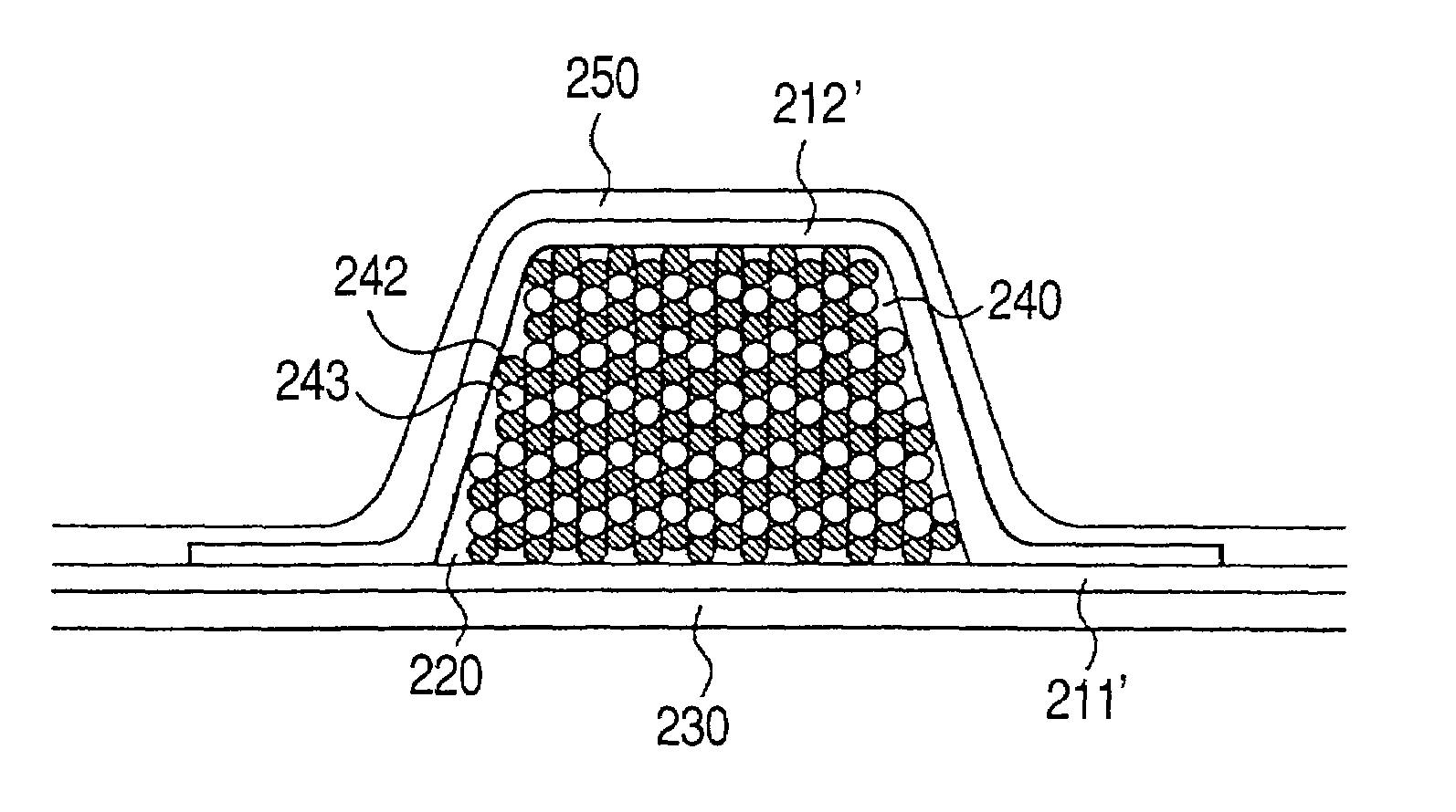
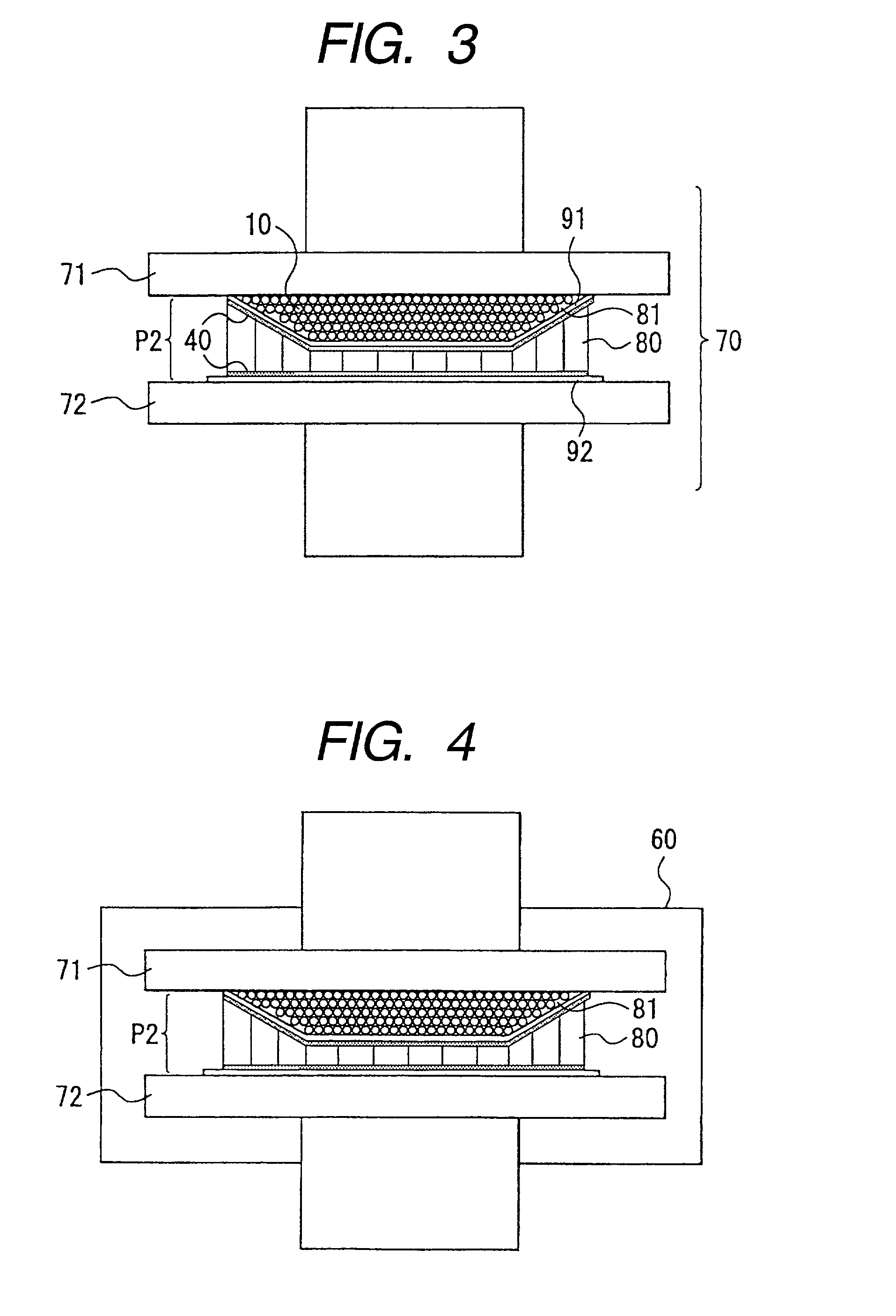
[0137]In this embodiment, with reference to FIG. 3, description will be made on a method in which skins 91 and 92 are bonded respectively with the upper and lower surfaces of a honeycomb core 80 so as to form a honeycomb sandwich panel by use of silicon balls 10 and a pressing machine 70. A recess portion 81 is provided on the upper surface side of the honeycomb core 80 as shown in FIG. 3. The upper skin 91 to be bonded with the upper surface of the honeycomb core 80 is molded into the same shape as the upper surface shape having the recess portion 81. On the other hand, the lower skin 92 like a flat plate is bonded with the lower surface of the honeycomb core 80.

[0138]First, surface treatment is carried out on the respective bonded surfaces of the honeycomb core 80, the upper skin 91 and the lower skin 92. The surface treatment can be carried out in a manner similar to that in the first embodiment. Next, a bonding adhesive 40 is applied onto the respective bonded surfaces, and the ...


PUM

PropertyMeasurementUnit
Temperatureaaaaaaaaaa
Fractionaaaaaaaaaa
Fractionaaaaaaaaaa

Abstract

There is provided a method for manufacturing a structural body comprising: a structural body formation step of forming the structural body by combining a plurality of constituent members through a bonding adhesive; a closed space formation step of disposing the structural body into a pressurizing or heating unit, forming a closed space with at least one of the structural body and the pressurizing or heating unit, and charging an elastic body into the closed space; a hardening step of fixing or hardening the bonding adhesive through the elastic body by the pressurizing or heating unit; and a discharge step of discharging the elastic body from the closed space.

Description

BACKGROUND OF THE INVENTION[0001]1. Field of Invention[0002]The present invention relates to a bonding method using spherical bodies made of silicon rubber.[0003]The present invention also relates to a method for manufacturing a structure (structural body) with a closed space, and particularly relates to a method for manufacturing a structure with a closed space in which a structure with a closed space made of a fiber reinforced resin composite material is formed integrally by bonding without using any mechanically coupling unit such as rivets, so that the labor and cost for manufacturing can be reduced, and the manufacturing cycle can be accelerated.[0004]The present invention also relates to a method for manufacturing a composite material stiffened panel, and particularly relates to a method for manufacturing a composite material stiffened panel by use of a flexible mandrel.[0005]The present invention also relates to a method for manufacturing a structure with a closed space.[0006...

Claims


Application Information

Patent Timeline
IPC IPC(8): B28B7/30B29C70/44
CPCB29C43/10B29C70/086B29C70/44B29C70/46B29C33/20B29C70/30B29K2105/0854B29C2043/3655B29K2083/00B29K2105/06B29C70/443
Inventor MIURA, JUNJIHARADA, ATSUSHIMARUYAMA, SEIJIYAMAGUCHI, EIKATSUTOI, YASUHIRO
Owner SUBARU CORP
Why Eureka
Try Eureka