Multi-touch sensing light emitting diode display and method for using the same

a technology of light emitting diodes and touch sensors, applied in the direction of counting objects on conveyors, pulse techniques, instruments, etc., can solve the problems of increasing cost and complexity in component layout and wiring, prone to false triggering of occlusion-based approaches, etc., and achieve the effect of improving the accuracy of touch sensors

Inactive Publication Date: 2009-10-06
NEW YORK UNIV
View PDF6 Cites 137 Cited by
  • Summary
  • Abstract
  • Description
  • Claims
  • Application Information

AI Technical Summary

Benefits of technology

[0010]It is one of the objects of the present invention to improve the accuracy of a touch sensor of the kind that uses an LED array in a bidirectional manner.
[0011]Another one of the objects of the present invention is to eliminate the need for any additional illumination, external or internal, for a sensor of this kind.
[0012]Still another object of the present invention is to eliminate the need for any additional opto-electronic elements for a sensor of this kind.
[0018]When the array consists of multi-chip LEDs with individually addressable electrodes, as can be the case in multi-color displays, the illumination provided for touch sensing can also be generated by operating, e.g., only one of the chips within each LED package as an emitter, while an alternate chip operates as a detector. In this exemplary configuration according to one exemplary embodiment of the present invention, the spatial interleaving of LED function may not be needed, and both lighting and sensing can be performed at all pixels simultaneously.
[0020]Because the illumination used for active optical sensing can come from the LED array itself, the need for any additional or ambient light source is eliminated or at least reduced. Also, because the light sought for sensing purposes comes from only the device itself, the signal thresholds used for resolving the presence of a finger can be much more narrowly defined, thus producing more accurate results. Because the light emitted during the scan process is spatially localized to the area being actively sensed, sensing accuracy is again improved.
[0023]The exemplary process of touch sensing can thus be driven very quickly, and performed such that momentary lighting and blanking of LEDs is negligibly perceptible.

Problems solved by technology

However, this occlusion-based approach may be prone to false triggering by shadows.
Finally it does not apply to passive-matrix configurations, and hence is not scalable in practice to large arrays.
However, this approach likely needs the addition of a large number of dedicated photo-detectors, resulting in increased cost and complexity in component layout and in wiring.
Furthermore, such arrangement may still be prone to false triggers due to external illumination.

Method used


Image

  • Multi-touch sensing light emitting diode display and method for using the same
  • Multi-touch sensing light emitting diode display and method for using the same
  • Multi-touch sensing light emitting diode display and method for using the same

Examples


Embodiment Construction

[0041]Exemplary embodiments of the present invention will be described with reference to the attached drawings. These drawings illustrate the invention but do not restrict its scope, which should be determined solely from the appended claims.

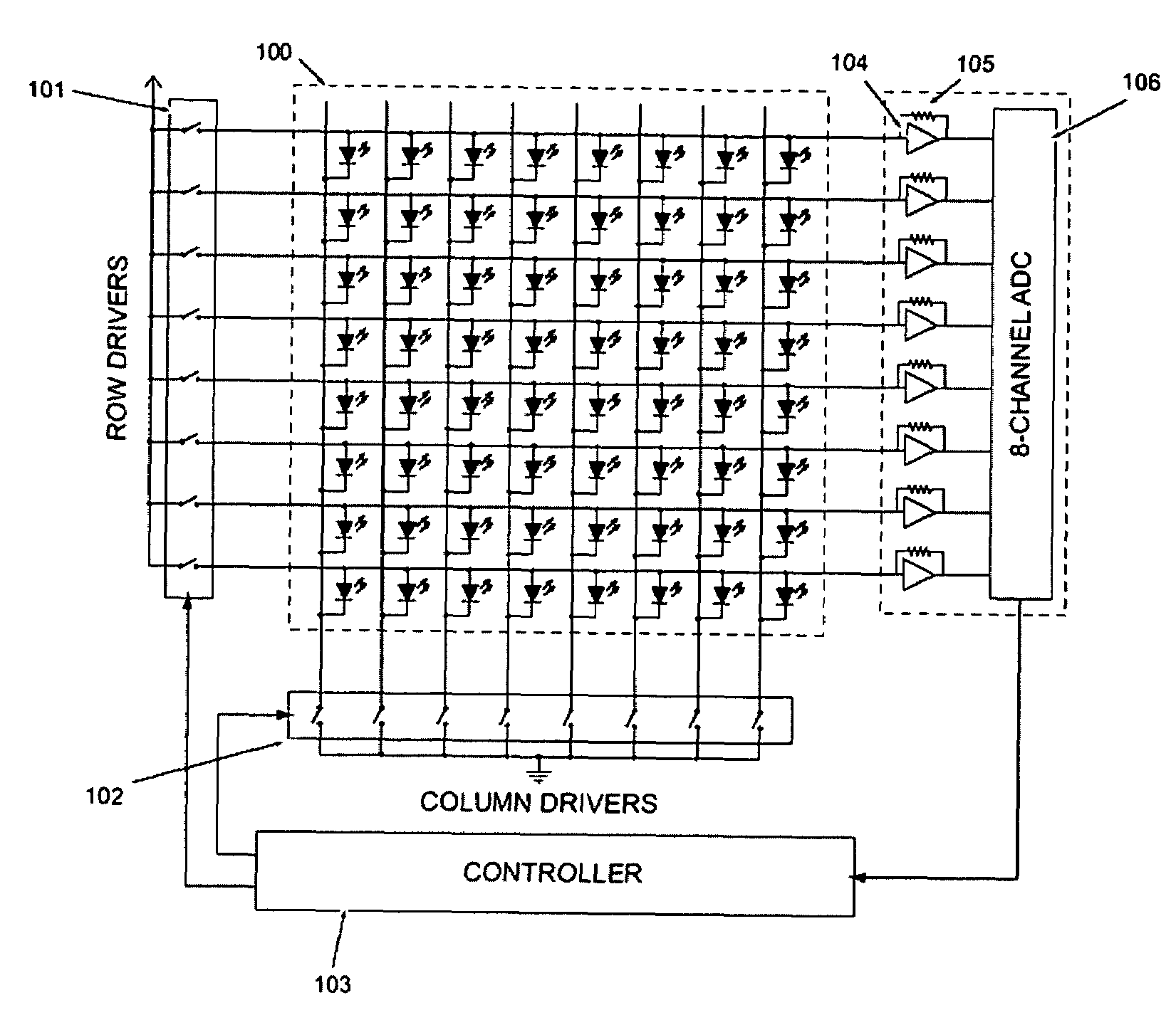
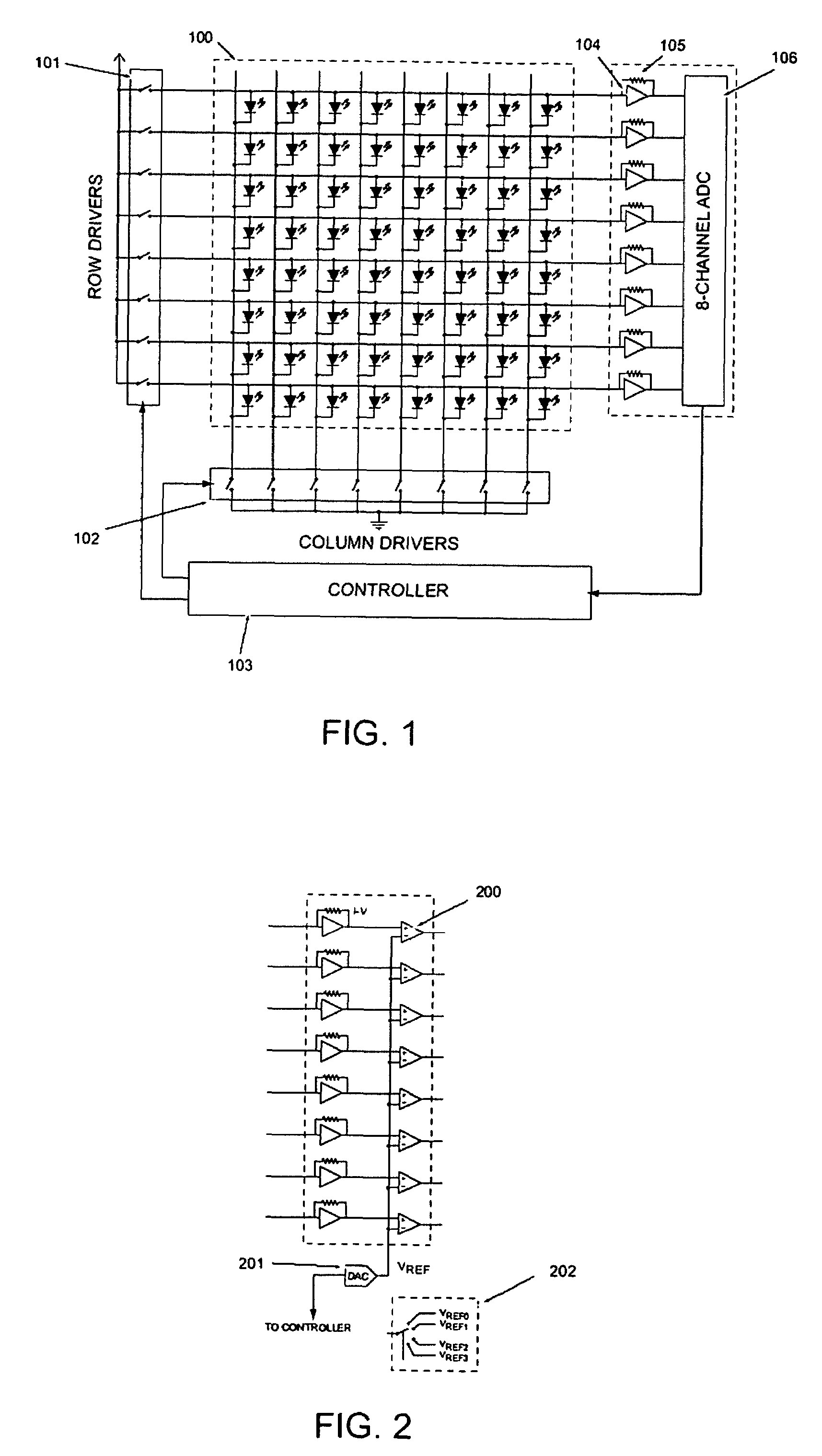
[0042]For example, FIG. 1 shows an exemplary embodiment of an arrangement according to the present invention which includes an array of individual LEDs 100 that are connected in a matrix row / column configuration as is typical for arrays designed for display purposes. For example, all LED anodes for a given row are connected together to constant-current unipolar row source drivers 101. Similarly, the cathodes for all the LEDs in a given column are connected together to unipolar column sink drivers 102. These drivers can be MOSFETs. Under the control of a controller 103, the array 100 can display graphical information by sequentially enabling each of the column drivers in turn, while row drivers can be enabled or disabled according to the desired ...


PUM


Abstract

Apparatus and method for both displaying graphical output and for sensing, e.g., multi-touch input are provided. A light-emitting diode (“LED”) matrix-array may be configured to both emit and sense light. The array may be driven in such a way so as to enable the array itself to act as the illumination source preferable for either reflective or scattering optical touch sensing. The need for additional opto-electronic components, or an external illumination source, is thus eliminated or at least reduced, and sensing accuracy is likely improved. Additionally, the method is practical for large dimensions.

Description

CROSS-REFERENCE TO RELATED APPLICATION(S)[0001]This application claims priority from U.S. Patent Application No. 60 / 621,379, filed on Oct. 22, 2004, the entire disclosure of which is incorporated herein by reference.FIELD OF THE INVENTION[0002]The present invention relates generally to light emitting diode (“LED”) display devices, and more particularly to LED displays that are touch-input enabled, and methods for using the same.BACKGROUND INFORMATION[0003]Light emitting diodes (“LEDs”) are compact inexpensive solid-state devices which produce light when a suitable electric current is applied. They are extensively used as display indicators for electronic and computing devices. They are also widely used in large arrays to display graphics and text information in raster form.[0004]Operating an array of LEDs to display graphical data is typically performed by connecting them in a passive-matrix configuration and driving them column by column in a time-multiplexed manner. During each co...

Claims


Application Information

Patent Timeline
Patent Type & Authority Patents(United States)
IPC IPC(8): G09G5/00
CPCG06F3/0421H03M11/26H03K17/9631H03K17/9629
Inventor HAN, JEFFERSON Y.
Owner NEW YORK UNIV
Why Eureka
Try Eureka