Optical scanning device and image forming apparatus

a scanning device and image forming technology, applied in the direction of recording devices, instruments, optical elements, etc., can solve the problems of insufficient reduction of visible image displacement in some cases, inability to detect sync signals with high accuracy, and difficulty in minimizing visible image displacemen

Inactive Publication Date: 2009-10-06
RICOH KK
View PDF15 Cites 792 Cited by
  • Summary
  • Abstract
  • Description
  • Claims
  • Application Information

AI Technical Summary

Benefits of technology

[0010]It is an object of the present invention to at least partially solve the problems in the conventional technology.

Problems solved by technology

Even if the timings of driving the beam-emitting units are so adjusted, the displacement of the visible images cannot be sufficiently reduced in some cases.
The phases of these sync signals cannot be detected with high accuracy, which makes it difficult to minimize the displacement of visible images.

Method used


Image

  • Optical scanning device and image forming apparatus
  • Optical scanning device and image forming apparatus
  • Optical scanning device and image forming apparatus

Examples


Embodiment Construction

[0033]Exemplary embodiments of the present invention will be explained in detail below with reference to the accompanying drawings.

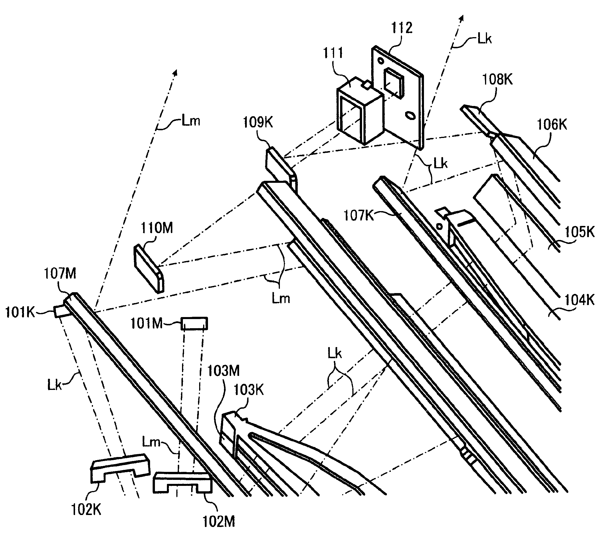
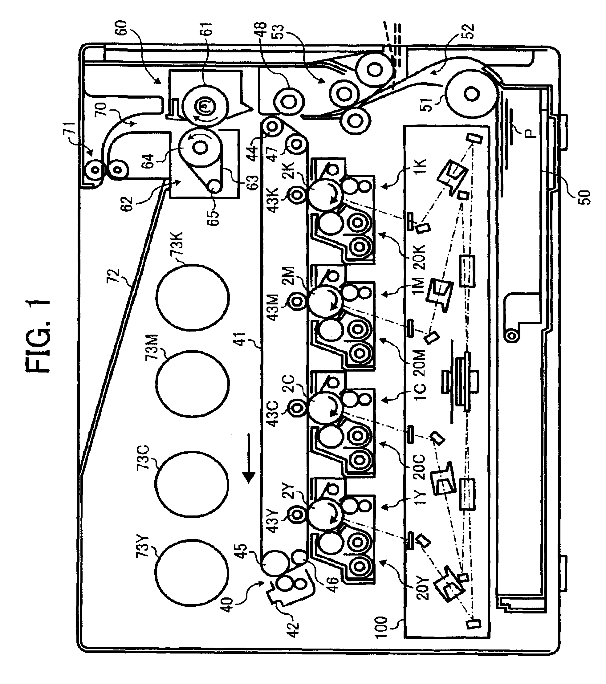
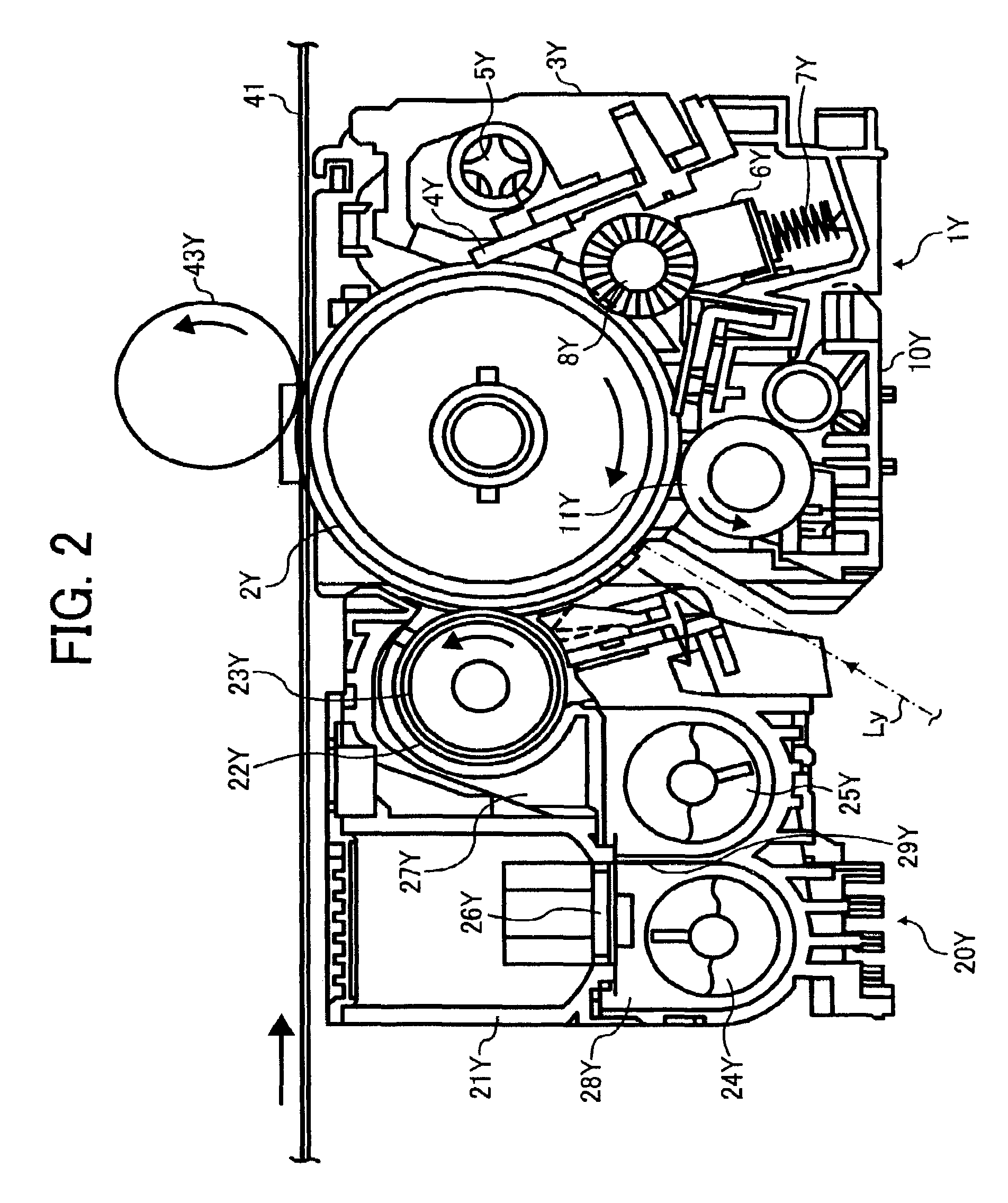
[0034]FIG. 1 is a schematic configuration diagram of an electronic-photographic-type printer (hereinafter, “a printer”). As shown in FIG. 1, the printer includes process cartridges 1Y, 1C, 1M, and 1K and developing units 20Y, 20C, 20M, and 20K. The process cartridges 1Y, 1C, 1M, and 1K contain yellow toner, cyan toner, magenta toner, and black toner, respectively. The developing units 20Y, 20C, 20M, and 20K are used to develop yellow images, cyan images, magenta images, and black images, respectively. Nonetheless, the four cartridges are of the same configuration, and so are the four developing units 20Y, 20C, 20M, and 20K. They are replaced by new ones when their lifetime expires. The process cartridge 1Y containing Y toner, for example, includes a drum-shaped photoconductor 2Y, a drum cleaning unit 3Y, a discharging lamp (not shown), a charger 10Y, and...


PUM


Abstract

A deflecting unit deflects a light beam emitted by each of a plurality of light-beam emitting units independently to scan surfaces of different bodies to be scanned. Each of a plurality of light-receiving units receives the deflected light beam at a predetermined position in a direction of the deflection. An incident angle of the deflected light beam with respect to a scanning line extending in a direction of scanning on a light-receiving surface of the light-receiving unit is set to be identical for all of the light-receiving units.

Description

CROSS-REFERENCE TO RELATED APPLICATIONS[0001]The present document incorporates by reference the entire contents of Japanese priority document, 2005-225004 filed in Japan on Aug. 3, 2005.BACKGROUND OF THE INVENTION[0002]1. Field of the Invention[0003]The present invention relates to an optical scanning device that deflects light beams emitted from a plurality of beam-emitting units independently thereby scanning surfaces of different objects to be scanned, and that includes a light-receiving unit for receiving each of the deflected scanning beams at a predetermined position in the direction of deflection.[0004]2. Description of the Related Art[0005]Conventionally, optical scanning devices are widely used in digital image forming apparatuses. The optical scanning devices include a beam-emitting unit and a beam-deflecting unit. The beam-emitting unit includes a laser diode or the like and emits a light beam. The beam-deflecting unit is, for example, a polygon mirror that rotates or an ...

Claims


Application Information

Patent Timeline
Patent Type & Authority Patents(United States)
IPC IPC(8): B41J2/435B41J2/47
CPCG02B26/123H04N1/506H04N1/40037G02B26/127
Inventor TOMITA, YASUMASA
Owner RICOH KK
Why Eureka
Try Eureka