Method for manufacturing hydro dynamic bearing device

a technology of hydrodynamic bearings and manufacturing methods, applied in mechanical equipment, manufacturing tools, instruments, etc., can solve the problems of reducing working efficiency, becoming too burdensome for workers, and complicated and hard work to complete, and achieve the effect of efficient wiping

Active Publication Date: 2009-10-13
NTN CORP
View PDF15 Cites 0 Cited by
  • Summary
  • Abstract
  • Description
  • Claims
  • Application Information

AI Technical Summary

Benefits of technology

[0021]The present invention has been completed in consideration of the above circumstances. It is a technical object of the present invention to provide a method and an apparatus for manufacturing a hydro dynamic bearing device that allows a worker to properly and efficiently perform a finishing treatment for dealing with the lubricating oil after lubricating the hydro dynamic bearing device, more specifically to properly and efficiently wipe the lubricating oil adhering to the outside area of the housing and adjust an oil level height of the lubricating oil being filled in the inside of the housing.

Problems solved by technology

In this case, however, a large amount of the lubricating oil adhere to various parts of the removed hydro dynamic bearing device, for example to the outer peripheral surface and the outer bottom surface of the housing, the outer end face of the sealing part, and the outer end face of the axial member.
However, when the lubricating oil is wiped off using the resin film or the like as described above, the wiping is a complicated and very hard work that takes much time to complete, while becoming too burdensome for the worker.
Consequently, there is a possibility of decreasing the working efficiency.
In this method, furthermore, there is a tendency that it becomes difficult to properly wipe the lubricating oil off from each of the above parts.
As a result, it is concerned about the quality of the product which may decrease.
Consequently, there is a possibility that it becomes difficult to wipe off the lubricating oil on the outer end face of the sealing part and the outer end face of the axial member, and it is difficult to prevent the lubricating oil being remained in place.
Therefore, the management of the oil-level height of the lubricating oil in the housing may be difficult since variations in absorbing volume may occur.
When the above variations cause a shortage of the lubricating oil in the housing, several troubles occur, for example insufficient lubrication of the bearing device.
Consequently, the hydro dynamic bearing device may deteriorate earlier than expected.
In addition, when the amount of the lubricating oil in the housing is excessive, there is a possibility of causing a leakage of the lubricating oil to the outside when the hydro dynamic bearing device is operated at an upper-limit temperature of the operation.

Method used


Image

  • Method for manufacturing hydro dynamic bearing device
  • Method for manufacturing hydro dynamic bearing device
  • Method for manufacturing hydro dynamic bearing device

Examples


Embodiment Construction

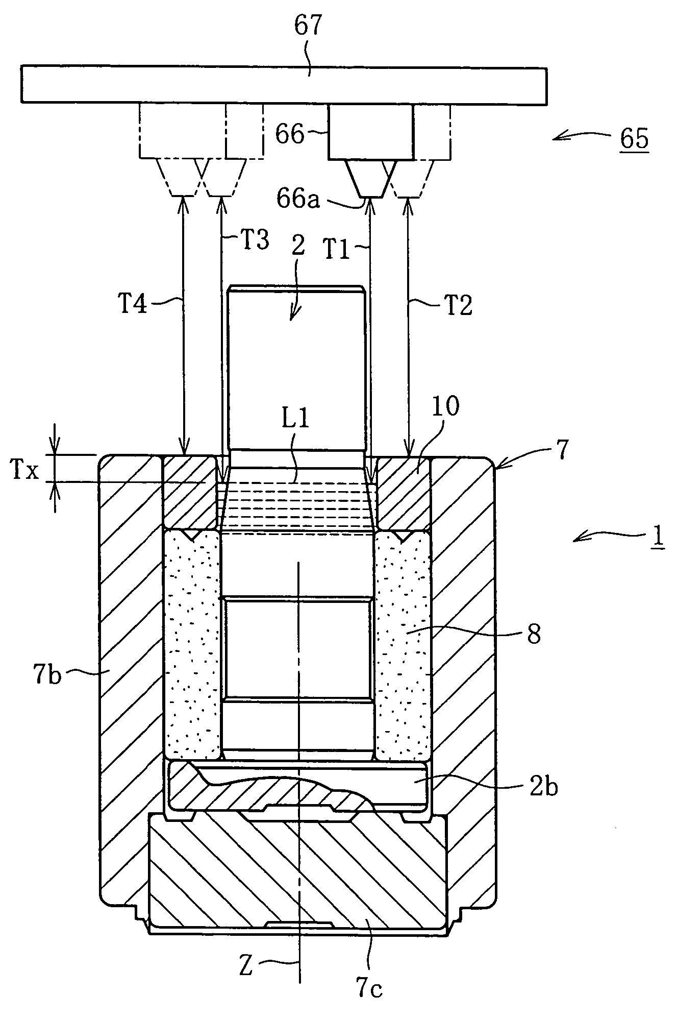
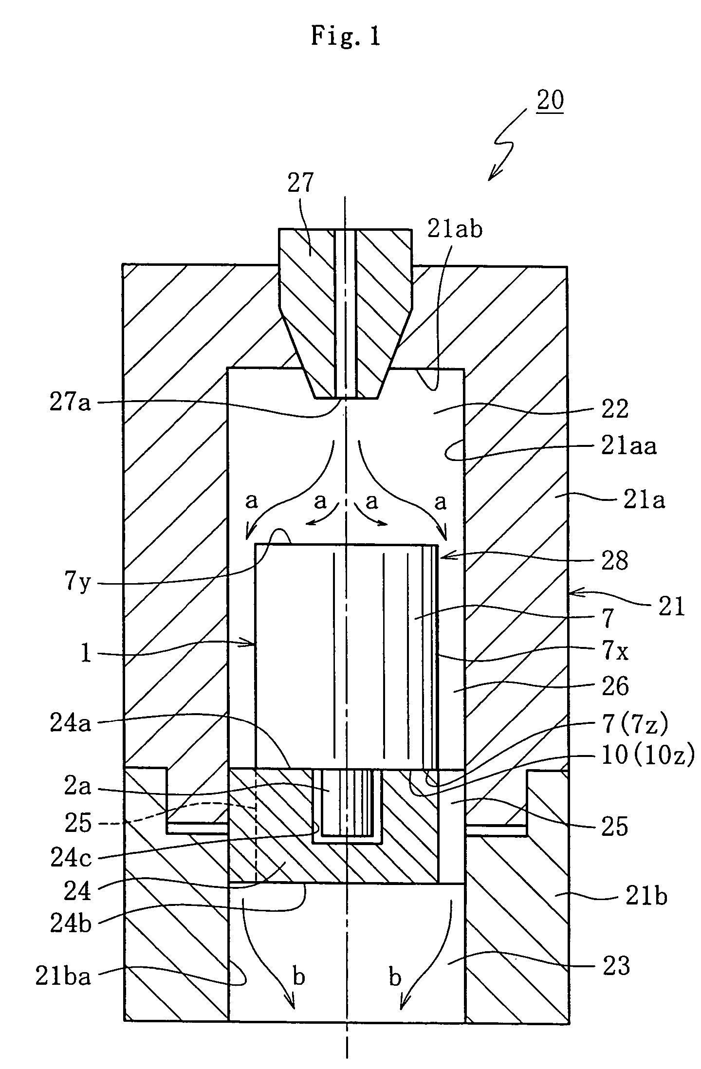
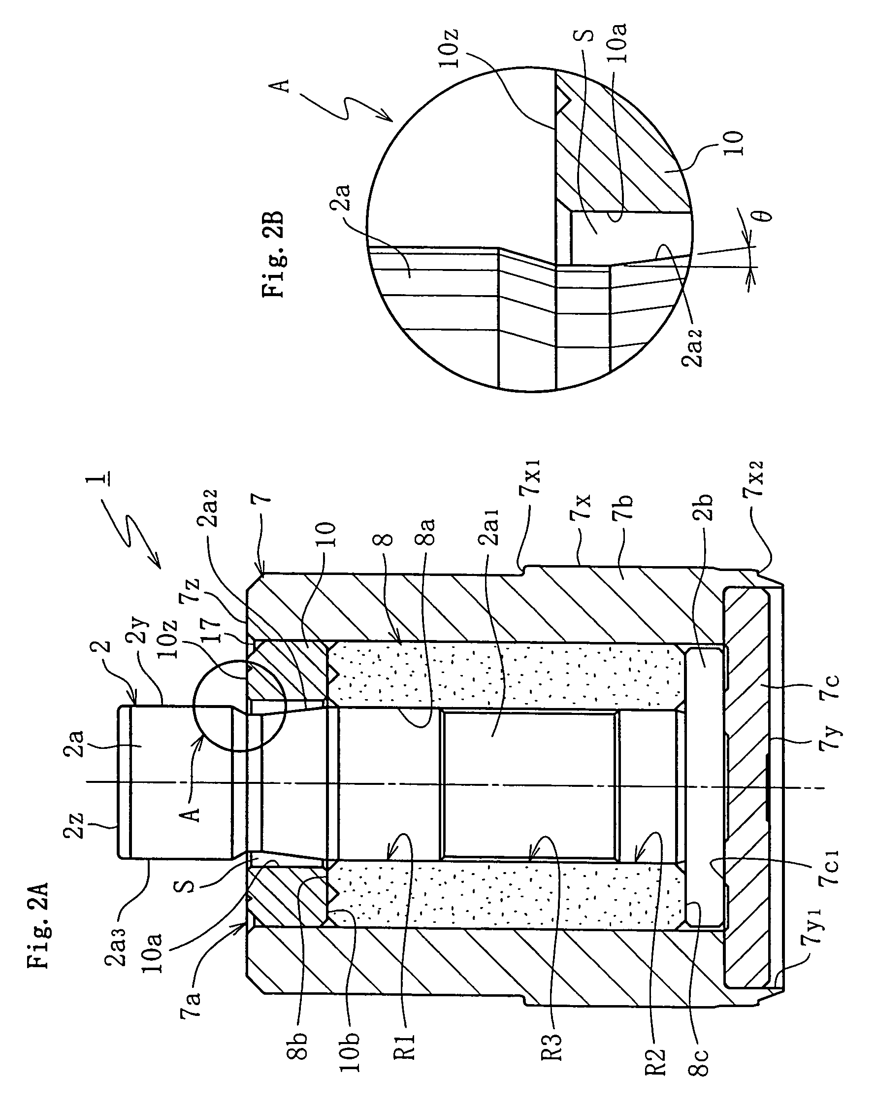
[0063]Hereinafter, preferred embodiments of the present invention will be described with reference to the accompanying drawings. FIG. 1 is a schematic view of an apparatus for wiping-off lubricating oil as a first manufacturing apparatus for carrying out a first method for manufacturing a hydro dynamic bearing device in accordance with the present invention. FIGS. 2A and 2B are diagrams for illustrating the inner structure of the hydro dynamic bearing device, FIG. 2A being a vertical cross sectional view thereof, and FIG. 2B being an enlarged view of a part marked with the symbol A in FIG. 2A.

[0064]For the sake of convenience in description, the configuration of a hydro dynamic bearing device will be described at first in advance to the description of a wiping-off apparatus for carrying out the first manufacturing method.

[0065]As shown in FIG. 2A, the hydro dynamic bearing device 1 mainly includes a housing 7 in a bottomed cylindrical shape having an opening part 7a in its one end, ...


PUM

PropertyMeasurementUnit
angleaaaaaaaaaa
removing speedaaaaaaaaaa

Abstract

A method for manufacturing a hydro dynamic bearing device is provided for the finishing treatment of lubricating oil after lubricating the hydro dynamic bearing device. The hydro dynamic bearing is constructed of an axial member housed in a housing, a radial bearing part for supporting the axial member in a non-contact manner in a radial direction by a hydro dynamic pressure action of the lubricating oil generated in a radial bearing clearance, and a sealing part arranged in an opening part of the housing, and the method has the step of measuring the oil-level height of the lubricating oil in the housing by a laser detector.

Description

CROSS-REFERENCE TO RELATED APPLICATION[0001]This application is a divisional application of, and claims the priority benefit of, U.S. application Ser. No. 10 / 402,321 filed on Mar. 28, 2003 now U.S. Pat. No. 7,040,019.BACKGROUND OF THE INVENTION[0002]1. Field of the Invention[0003]The present invention relates to a method and an apparatus for manufacturing a hydro dynamic bearing device. In particular, the present invention relates to a method and an apparatus for manufacturing a hydro dynamic bearing device to be used in a spindle motor equipped in an information technology device such as a magnetic disk device (e.g., HDD or FDD), an optical disk device (e.g., CD-ROM, CD-R / RW, or DVD-ROM / RAM, and an optical magnetic disk device (e.g., MD or MO), a scanner motor equipped in a copying machine, a laser printer (LBP), a barcode reader, or the like, or a small-sized motor equipped in an electrical equipment such as an axial fan.[0004]2. Description of the Related Art[0005]As is generally...

Claims


Application Information

Patent Timeline
Patent Type & Authority Patents(United States)
IPC IPC(8): B21K1/10
CPCF16C33/10F16C33/103F16C41/008Y10T29/53022Y10T29/5303Y10T29/53104Y10T29/49769Y10T29/53039Y10T29/51Y10T29/49639Y10T29/49636
Inventor KAIMI, MASAYUKISHIMIZU, KAZUTOBITOU, KIMIHIKOISHIYAMA, NAOYAMASHITA, NOBUYOSHI
Owner NTN CORP
Why Eureka
Try Eureka