
Unitary molded corner piece method and apparatus

a corner piece and unitary molding technology, applied in mechanical apparatus, building scaffolds, manufacturing tools, etc., can solve the problems of high precision required, poor practicability of prior art system approach, and high requirements of marousek system, especially on multi-story building units requiring window surrounds

Inactive Publication Date: 2009-10-13
RLC TECH
View PDF15 Cites 12 Cited by
  • Summary
  • Abstract
  • Description
  • Claims
  • Application Information

AI Technical Summary

Benefits of technology

[0034]Molded one piece novel corner also minimizes installation time and eliminates water infiltration behind the corners.

Problems solved by technology

From an engineering standpoint the system of Marousek may form the desired water tight channel, but if so it does it only at a high cost of the precision required.
Indeed, since some of his J channels must be cut to exact length and must be cut as square as possible, this prior art system approach suffers in many practical applications.
For example, the Marousek system requirements, especially on multi story building units requiring window surrounds, is highly impractical.
Workers on ladders or scaffolding simply cannot take the time to measure with great precision and repeatedly go up and down for trial and error multiple vinyl J channel cuts.
Even if the workers call out such precise requirements to those on the ground or lower levels, the square cuts of great precision are hard to achieve in a speedy and economical manner.
The prior art Left and Right directionality causes both stocking and assembly problems.

Method used


Image

  • Unitary molded corner piece method and apparatus
  • Unitary molded corner piece method and apparatus
  • Unitary molded corner piece method and apparatus

Examples


Embodiment Construction

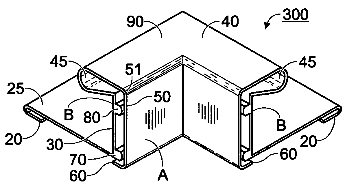
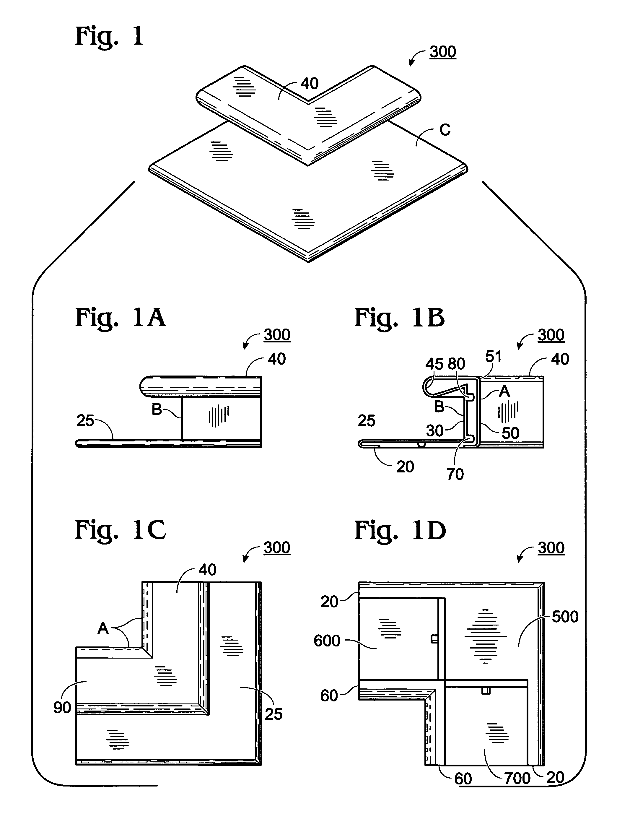
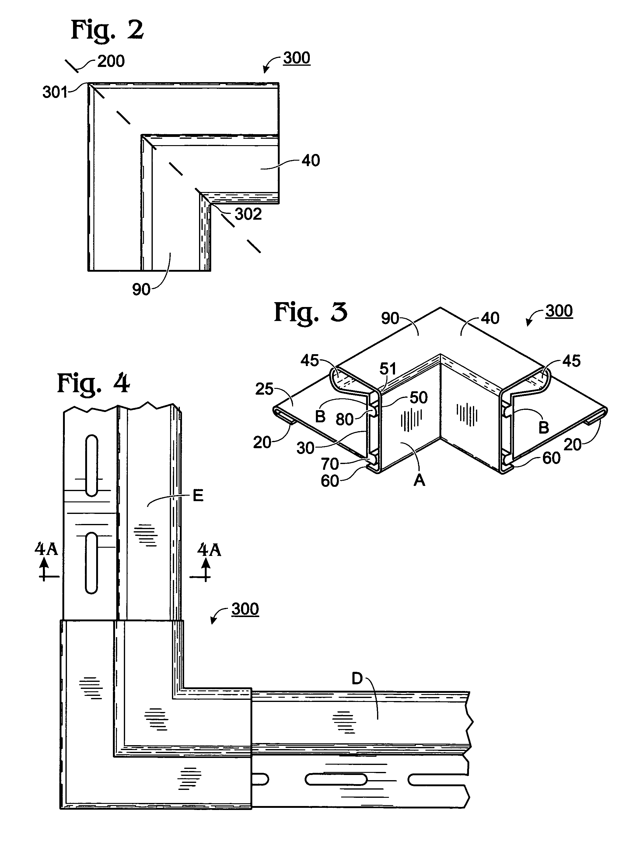
[0037]The invention will be described by reference to the several views hereof. Please collectively see FIGS. 1 through 5.

[0038]In particular, FIG. 1 shows a top perspective taken from outside the corner piece invention 300. Refer briefly to FIG. 1C, a top view looking down; area A is referred to herein as the “inside” of corner piece 300. Thus, the acute dimension of the corner 300 is referred to as the inside, whereas the greater arc obtuse dimension is referred to as the “outside” of the corner piece 300.

[0039]Digressing momentarily, FIG. 1A is a side view depicting one side of FIG. 1, and FIG. 1B is the other side of corner piece 300. FIG. 1D is a bottom view. These various views of FIG. 1 have walked around the corner piece 300 and have shown novel features that provide a versatility not found anywhere in the art, prior to the advent of this invention. Such features are described in more detail by reference to other figures of my invention as described further below.

[0040]The “...


PUM


Abstract

A unitary molded corner piece, shaped as a right angle V, has a grooved base with slide openings on adjacent sides of the base for receiving and joining together a pair of orthogonally oriented J channel pieces in an assembly. Right angles of the unitary corner piece are spaced apart and defined by spaced vertical walls shaped as an inner and outer angle. Such angles are joined together at the top of the vertical walls by a closed loop. Two orthogonal oriented J channels slide into the corner base while a J channel vertical wall and a J channel top piece slide within the space defined between the vertical walls of the right angle V of the corner piece. A loose free end of the J channel fits within the adjoining loop of the corner piece. Reinforcing ribs in a J channel receiving pocket both frictionally hold a J channel inserted into said corner piece and guide water as a trough.

Description

PREVIOUS FILING INFORMATION[0001]This is an original filing of a regular utility patent application. The contents and filing date of a Provisional Application No. 60 / 761,694 filed on Jan. 23, 2006 by the same inventor hereof and having confirmation No. 3332 is mandated. Priority of that Provisional Application is claimed, and the contents and benefits thereof are incorporated herein by reference, as though that Provisional Application were set forth in full at this point.BACKGROUND OF THE INVENTION[0002]This invention is made by a sole inventor without any sponsorship of government funds.Field of the Invention[0003]This field of the invention relates generally to construction and the building trades; and, more particularly, to the field of forming window surrounds using vinyl J channel molding strips. This corner invention is identified by an adopted name and design of Kwik Corner™. My web site, of the same name, describes some features, advantages and protection afforded both by my...

Claims


Application Information

Patent Timeline
Patent Type & Authority Patents(United States)
IPC IPC(8): E06B1/04E04C2/38E06B3/984
CPCE04F19/02E06B1/68Y10T403/73Y10T403/72Y10T403/725E06B3/9641F16B2200/65F16B2200/67
Inventor KLEIN, ROBERT D.
Owner RLC TECH
Learn More