Plate heat exchanger

a heat exchanger and plate technology, applied in the field of heat exchangers, to achieve the effect of increasing the pressure stability of the plate heat exchanger

Inactive Publication Date: 2009-10-13
MODINE MFG CO
View PDF19 Cites 10 Cited by
  • Summary
  • Abstract
  • Description
  • Claims
  • Application Information

AI Technical Summary

Benefits of technology

[0019]In a still further form of this aspect of the present invention, the recesses are defined by embossed sides of one of the plurality of first and second heat exchanger plates, the other side of the other of the plurality of first and second heat exchanger plates is substantially flat, and the first media is engine coolant and the second media is CO2 refrigerant of a vehicle air conditioner. According to a further form, a rod-like element is in the second collecting and distribution channels adapted to increase the pressure stability of the plate heat exchanger.

Problems solved by technology

In this device, all of the heat exchanger plates are difficult to manufacture, and the device may be viewed as still taking up more space than desired in many applications in which space limitations are critical.

Method used


Image

  • Plate heat exchanger
  • Plate heat exchanger
  • Plate heat exchanger

Examples


Embodiment Construction

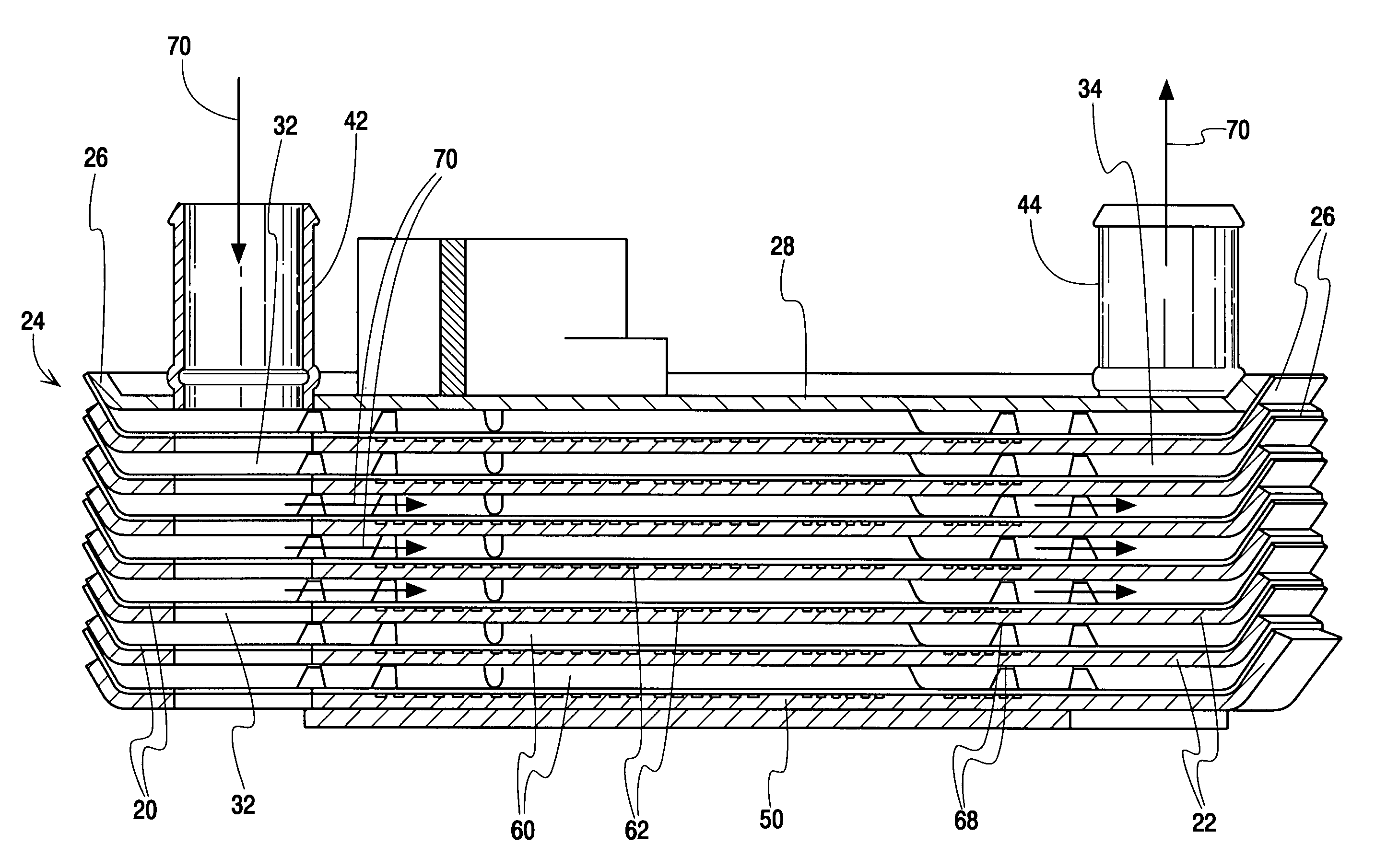
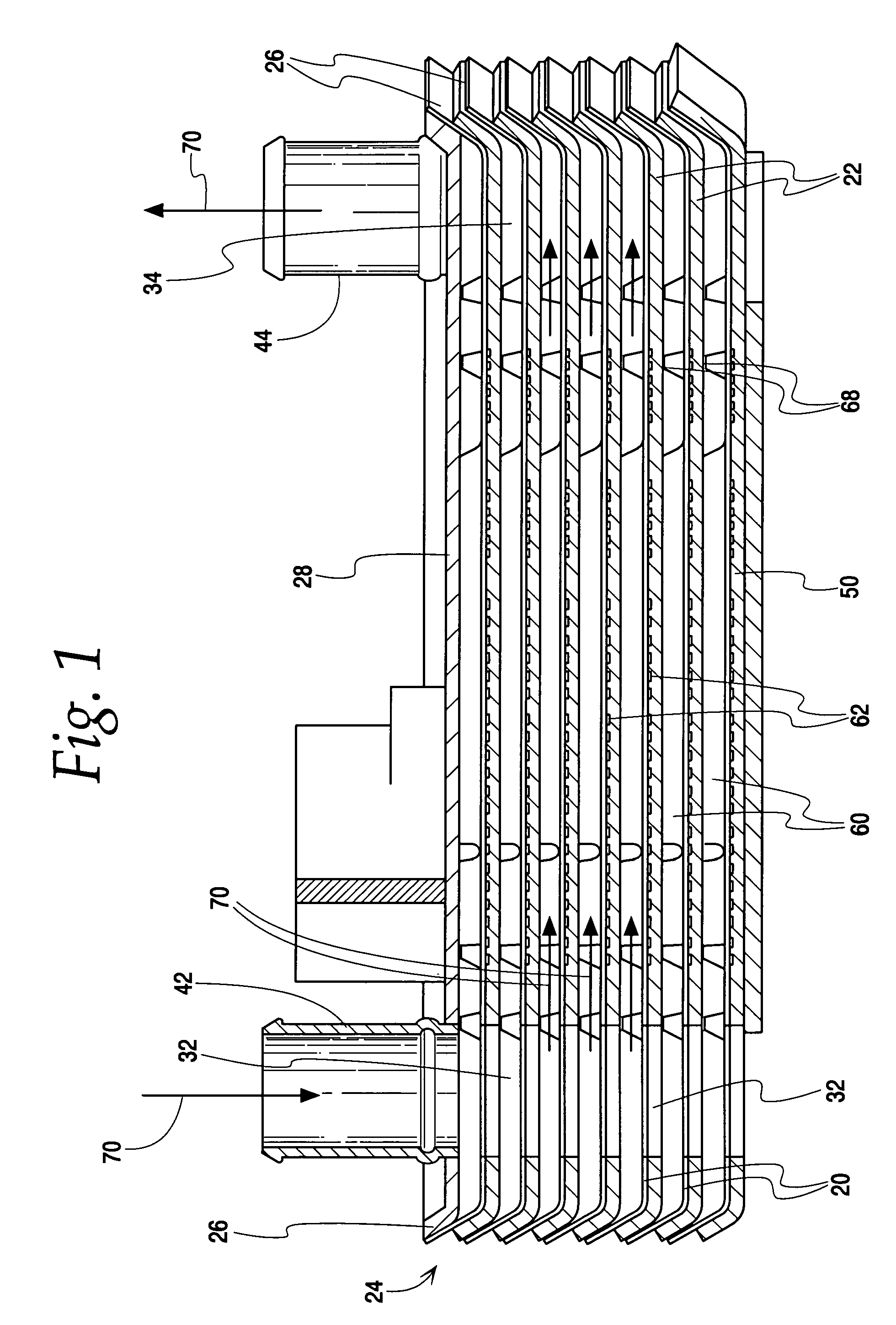
[0029]Plate heat exchangers according to the present invention may be advantageously used, for example, for heat exchange between the refrigerant (e.g., CO2) and the coolant of the a vehicle engine and, in such use, may be integrated in a suitable fashion both in the refrigerant loop of the air conditioner and in the coolant loop.

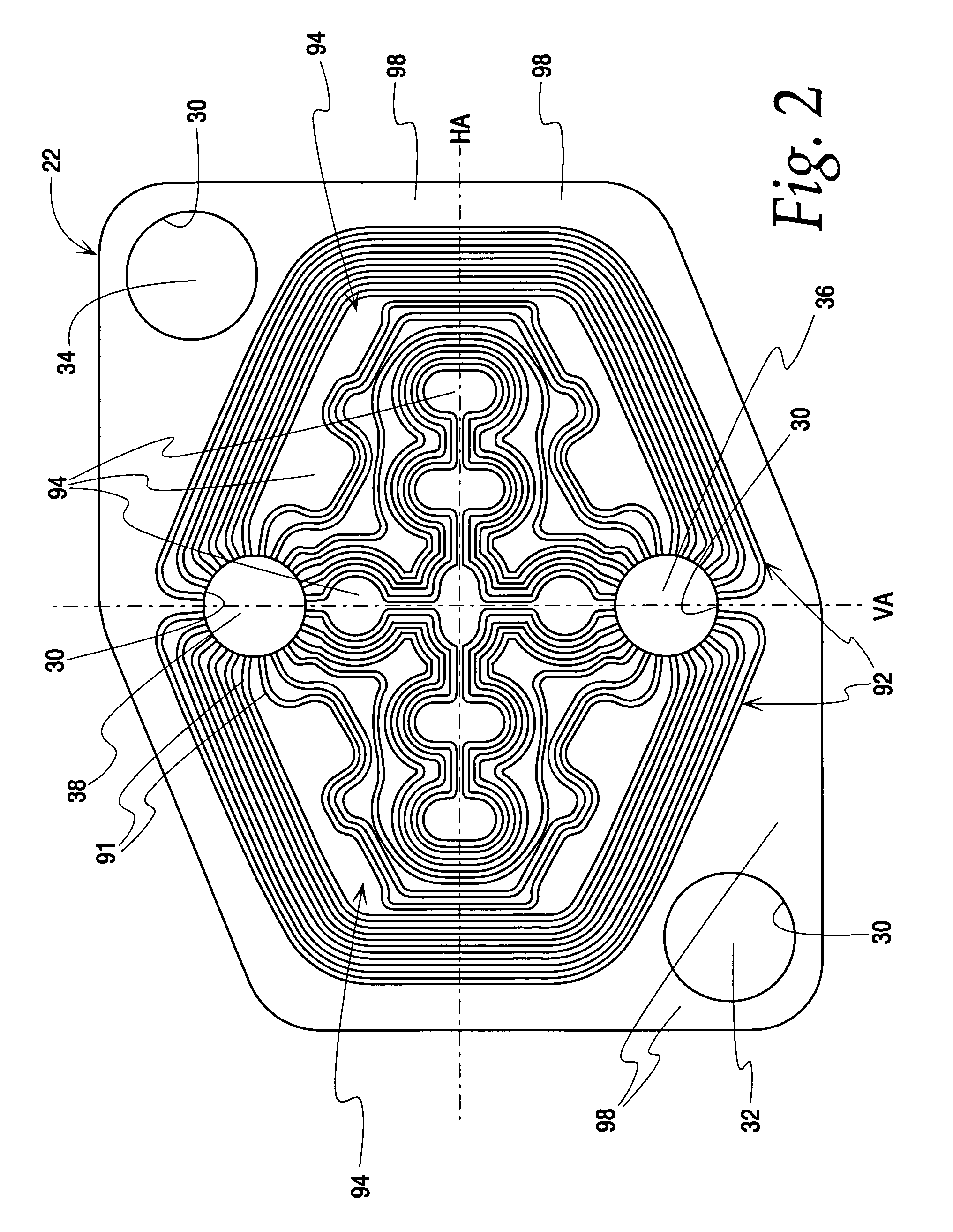
[0030]In the depicted embodiments, the plates 20, 22 of the plate heat exchanger 24 consist of aluminum sheets coated with solder. Though the plates 20, 22 are illustrated as hexagonally shaped as may be advantageously used in the described structure, it should be understood that plates which are not hexagonally shaped may be advantageously used within the scope of the present invention, with the shape chosen according to the intended use. The heat exchanger plates 20 and 22 are produced from aluminum sheets so as to be trough-like with a beveled edge 26 (in the FIG. 1 illustration, the edges 26 of the plates 20, 22 slope upward.).

[0031]Each plate 20, 22, a...


PUM


Abstract

A plate heat exchanger for exchanging heat between first and second media, including a plurality of first heat exchanger plates alternately stacked with a plurality of second heat exchanger plates between a base plate and a cover plate. The first and second heat exchanger plates have at least four passages therethrough which align to define a first collecting channel and a first distribution channel for the first media and a second collecting channel and a second distribution channel for the second media. First flow channels for the first media each are defined in a space between one side of the first heat exchanger plate and a facing one side of the adjacent second heat exchanger plate. Second flow channels for the second media each are defined between the other side of the first heat exchanger plate and the other side of the adjacent second heat exchanger plate. The second flow channels are defined by recesses defined in the surface of the other side of at least one of the first and second heat exchanger plates, and the other sides are metallically connected along their surfaces.

Description

CROSS REFERENCE TO RELATED APPLICATION(S)[0001]Not applicable.STATEMENT REGARDING FEDERALLY SPONSORED RESEARCH OR DEVELOPMENT[0002]Not applicable.REFERENCE TO A MICROFICHE APPENDIX[0003]Not applicable.TECHNICAL FIELD[0004]The present invention relates to a heat exchanger, and more particularly to a plate heat exchanger in which two different media alternately flow in heat exchange fashion in spaces between stacked plates of the heat exchanger.BACKGROUND OF THE INVENTION AND TECHNICAL PROBLEMS POSED BY THE PRIOR ART[0005]Plate heat exchangers of a type generally corresponding to those corresponding to the present invention are shown in EP 14 00 772 A2 (assigned to the assignee of this application, published Mar. 24, 2004) and corresponding U.S. Publication No. 2004 / 112579 A1 (also assigned to the assignee of this application, and published Jun. 17, 2004), the full disclosures of which are hereby incorporated by reference. The plate heat exchanger disclosed therein is suitable for hea...

Claims


Application Information

Patent Timeline
Patent Type & Authority Patents(United States)
IPC IPC(8): F28F3/08F28F1/02F28D9/00
CPCF28D9/0012F28F3/048F28D9/005F28F2210/10
Inventor STRAHLE, ROLANDBORST, DANIELVETTER, FRANKMARSCHNER, HERBERTWELCHNER, DANIEL
Owner MODINE MFG CO
Why Eureka
Try Eureka