Annular seal member

a technology of annule and seal, which is applied in the direction of brake systems, machines/engines, transportation and packaging, etc., can solve the problems of deteriorating reliability of seals, affecting the sealing effect, and preventing the sealing path from being obstructed, so as to achieve more stable sealing, improve the stability of the pressure release function, and secure the effect of the pressure introduction spa

Inactive Publication Date: 2014-08-26
ADVICS CO LTD
View PDF42 Cites 6 Cited by
  • Summary
  • Abstract
  • Description
  • Claims
  • Application Information

AI Technical Summary

Benefits of technology

[0020]According to the fourth aspect, the protrusion is further provided at the annular seal member of the first aspect. Therefore, the pressure introduction space and the communication state of the passage recess with the pressure introduction space are secured more stably, and the stability of the pressure release function is further improved.
[0021]According to the above-described annular seal member, the distance from the bottom of the concave part to the seal mating face is larger than the distance from the bottom of the inter-convex concave part formed between the first convex part and the second convex part, so that the concave part between the second convex part and the annular lip remains even when the seal member is compressed such that the inter-convex concave part is disappeared, and thus the pressure introduction space is secured more positively.
[0022]According to the above-described annular seal member, the concave part is annular, so that the overall circumferential region of the annular lip functions as a valve. Thus, it is possible to further suppress the non-uniformity in the valve opening pressure and to improve the seal performance and the durability of the annular lip.
[0023]According to the above-described annular seal member, the second convex part is configured by the continuous ridge in the circumferential direction except for a position of the passage recess, so that the variation at the respective circumferential parts of the concave part (pressure introduction space) is suppressed. Thus, the contact pressure (surface pressure) of the annular lip to the seal mating face is uniformed at the respective circumferential parts, so that the seal is stabilized.
[0024]Additionally, in the above-described annular seal member, the protrusion may be provided in the passage recess and extends from the starting end of the passage recess to the connection part of the passage recess and the recess part. Thus, it is possible to securely suppress the obstruction of the passage recess by the protrusion.
[0025]Also, in the above-described annular seal member, the protrusion may be provided at the connection part of the passage recess and the recess part, so that the passage recess is not narrowed by the protrusion. Therefore, it is possible to reduce a variation area of the fitting interference (i.e., variation area of a compressive reactive force) at the respective circumferential parts of the base part by narrowing the width of the passage recess, so that the valve opening pressure is stabilized.

Problems solved by technology

According to the annular seal member disclosed in JP-A-2008-144784, when a fitting interference is excessively increased due to non-uniformity in size and the like (when a diameter of the bottom face of the seal recess is smaller than a diameter of a base end of the lip part), a slit, which is provided as the pressure guidance path, is deformed in the vicinity of the base end of the lip part due to elastic deformation or creep deformation, so that the pressure guidance path is obstructed.
Also, when many pressure guidance paths are provided or a width of the pressure guidance path (slit) is increased so as to avoid the obstruction of the pressure guidance path, it is not possible to secure a straining force (surface pressure) that uniformly and sufficiently presses an inner diameter side of the annular seal member to an outer periphery of the shaft.
As a result, the reliability of the seal is deteriorated, so that a possibility of liquid leakage is increased.

Method used


Image

  • Annular seal member
  • Annular seal member
  • Annular seal member

Examples


Embodiment Construction

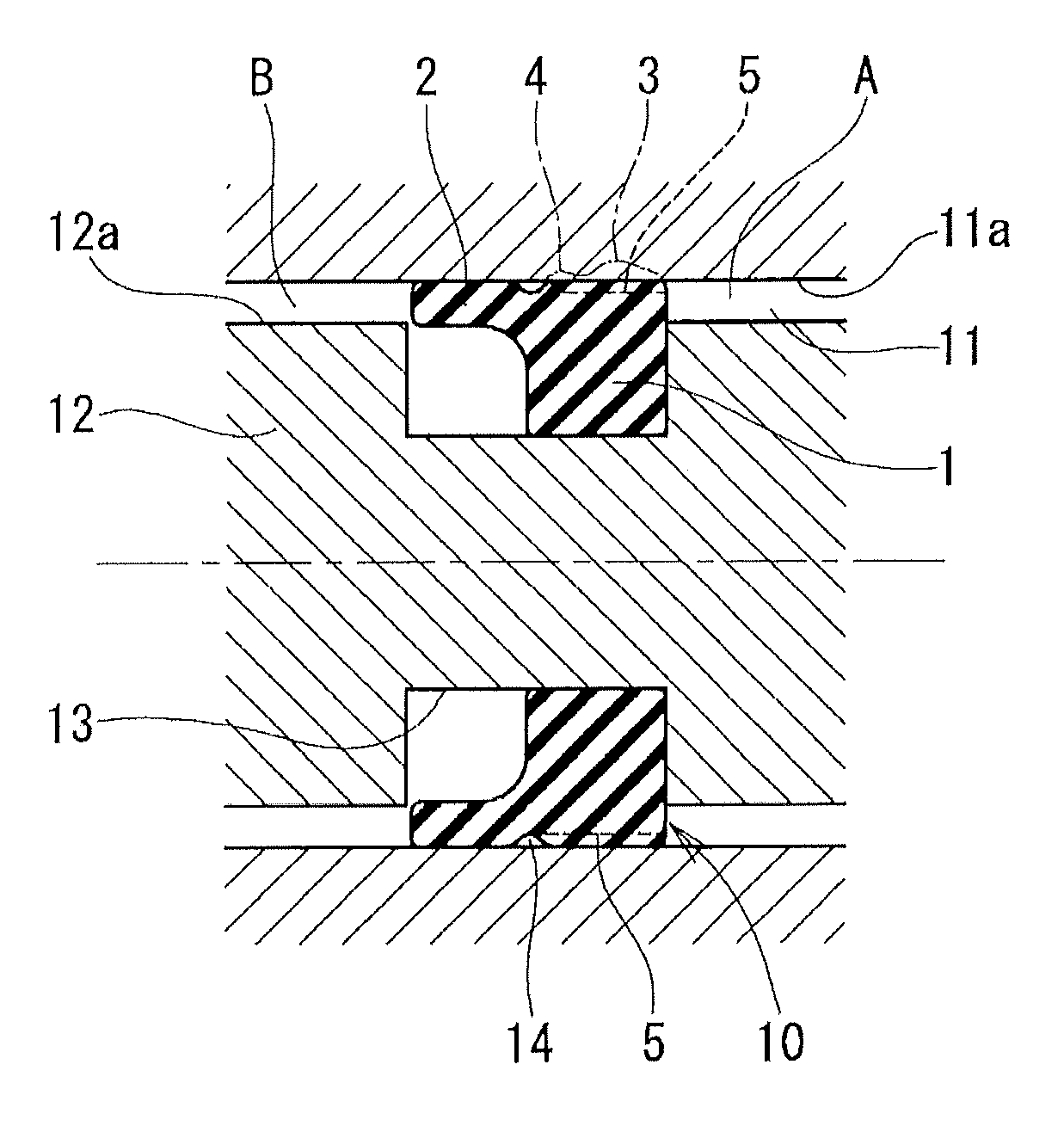
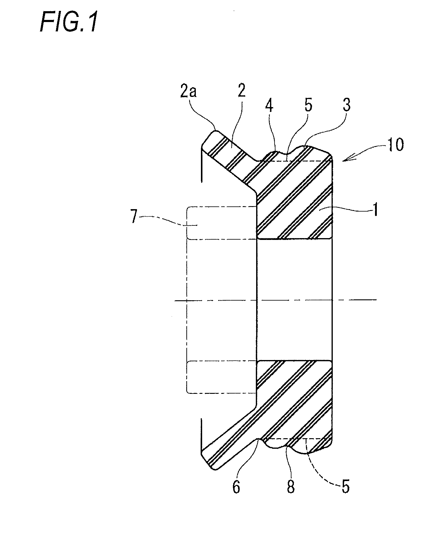
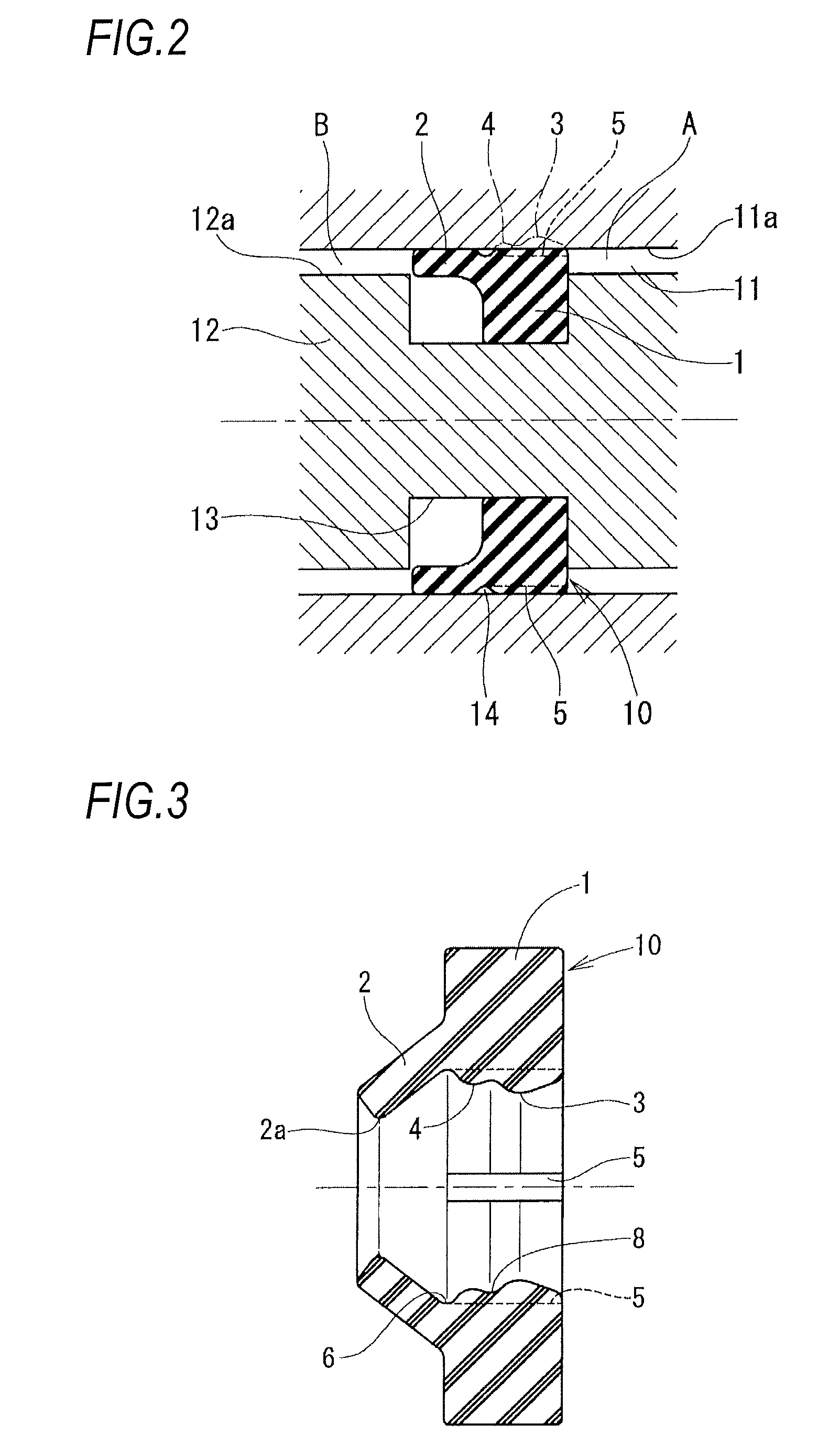
[0037]Hereinafter, illustrative embodiments of an annular seal member of this disclosure will be described with reference to FIGS. 1 to 10. An annular seal member 10 of a first illustrative embodiment shown in FIG. 1 has an annular base part 1, an annular lip 2 that axially extends from one end of the base part, a first convex part 3, a second convex part 4, a plurality of passage recesses 5 and a concave part 6. A rubber having hardness of 70 to 80 IRHD is used as the material.

[0038]The base part 1 of the annular seal member is inserted into a seal recess, which is formed at any one side of a shaft hole (which will be described later) and a shaft to be inserted into the shaft hole, so that it is arranged between a hole face of the shaft hole and an outer periphery of the shaft.

[0039]The annular lip 2, which is referred to as an outer periphery lip, obliquely extends from an one end of outer periphery of the base part 1 in an axial and diametrically outer direction and has a lip edg...


PUM


Abstract

An annular seal member configured to seal a gap between a shaft hole and a shaft inserted into the shaft hole, the annular seal member comprises: an annular base part; an annular lip, which includes a lip edge that is configured to be contact with one of a hole face of a shaft hole and an outer periphery of a shaft, the one of which is a seal mating face; a first convex part, a second convex part and a passage recess, which is provided at a face of the base part facing the seal mating face; a concave part, which is formed at a position between the second convex part and the base end portion of the annular lip, and which has a circumferential size larger than a recess width of the passage recess.

Description

CROSS-REFERENCE TO RELATED APPLICATION[0001]This application claims priority from Japanese Patent Application No. 2011-117160 filed on May 25, 2011, the entire subject matter of which is incorporated herein by reference.TECHNICAL FIELD[0002]This disclosure relates to an annular seal member that is used to seal a gap between a shaft and a shaft hole to be in a check state in a fluid pressure control apparatus or fluid pressure device. The check state is a state, in which a flow of pressure or liquid from one side to the other side of a space partitioned by a seal member is allowed and a flow of the pressure or liquid from the other side to one side is suppressed.BACKGROUND[0003]For example, JP-A-2008-144784 discloses an example of the annular seal member. The annular seal member (packing) disclosed in JP-A-2008-144784 has an annular base part and a lip part that axially extends from one end of the base part. Also, the annular seal member has a pressure guidance path on an outer perip...

Claims


Application Information

Patent Timeline
Patent Type & Authority Patents(United States)
IPC IPC(8): F16J15/32
CPCF16J15/164F16J15/064
Inventor OKAMURA, KEIFUKUDA, JUNICHIHISADA, YOSHITAKE
Owner ADVICS CO LTD
Why Eureka
Try Eureka