Liquid control system for double-fluid injector

A technology of liquid control and injector, which is applied in the direction of liquid injection device, injection device, and device for coating liquid on the surface, etc. It can solve the problem of inconsistency in glue supply volume, increase the overall size of the injector, and affect the consistency of glue points, etc. problem, achieve the effect of eliminating inconvenience, preventing liquid backflow and reducing shock

Active Publication Date: 2011-08-17
SHANGHAI UNIV
View PDF5 Cites 6 Cited by
  • Summary
  • Abstract
  • Description
  • Claims
  • Application Information

AI Technical Summary

Problems solved by technology

[0004] In the existing technical field, the glue spraying equipment used for electronic packaging is mainly based on mechanical jet dispensing and time-pressure dispensing, and their glue supply method is basically to put the glue liquid into the dispensing needle In the barrel, the glue is squeezed into the cavity of the glue injector with a compressed gas of constant pressure, and then different media are used to act on the glue to spray it out of the nozzle. There is a patent related to this (CN 101190429A) , the patent proposes a high-viscosity fluid micro-jet dispensing device. A bracket is installed next to the injection device to fix the dispensing syringe. After all the glue is used up, the glue is replaced again. This liquid supply method has the following disadvantages: First, because the syringe is fixed on the glue injector, the overall size of the injector is increased, and it takes up The space of a single glue injector is larger than that of a single glue injector, and it cannot realize the dispensing of some micro-sized devices; secondly, as the dispensing progresses, the glue in the syringe gradually decreases, and the volume occupied by the gas becomes larger and larger, but The input volume of the compressed gas has not changed, resulting in inconsistencies in the size of the glue supply before and after, which affects the consistency of the glue point

Method used


Image

  • Liquid control system for double-fluid injector
  • Liquid control system for double-fluid injector
  • Liquid control system for double-fluid injector

Examples


Embodiment 1

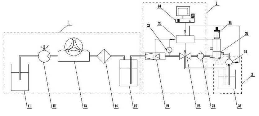
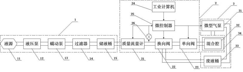
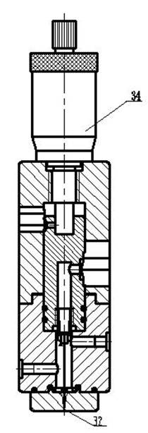
[0035] refer to figure 1 , figure 2 and image 3 , a liquid control system for dual-fluid injection, including a liquid source device (1), a liquid control device (2), a suction device (3) and a dual-fluid injector (34), characterized in that: the liquid source The device (1), the liquid control device (2), the dual-fluid injector (34) and the suction device (3) are sequentially connected through hoses to realize the liquid supply and liquid recovery of the dual-fluid injector.

Embodiment 2

[0037] refer to figure 1 , figure 2 and image 3 , this embodiment is basically the same as Embodiment 1, especially that the liquid source device (1) provides a liquid source for the system and ensures the existence of the working medium; the structure of the liquid source device (1) is: a The liquid source (11) is sequentially connected to a hydraulic pump (12), a peristaltic pump (13), a filter (14) and a liquid storage tank (15), and the hydraulic pump (12) and the peristaltic pump (13) have The signal port is connected with the microcontroller (25) in the liquid control device (2).

Embodiment 3

[0039] refer to figure 1 , figure 2 and image 3 , this embodiment is basically the same as Embodiment 1, the special feature is that the liquid control device (2) adjusts the flow of liquid, changes the flow direction, and provides constant flow, pulsating or continuous liquid to downstream equipment; the liquid source device The structure is: a mass flow meter (21) is sequentially connected to a liquid reversing valve (22) and a liquid check valve (23), the mass flow meter (21), liquid reversing valve (22) and liquid check valve The direction valves (23) all have signal ports, which are connected with the signal ports of the microcontroller (25), and the microcontroller (25) is connected with the industrial computer (24) and set parameters through the industrial computer (24), the quality The outlet of the flow meter (21) is provided with a flow display meter (26), and its display signal is transmitted to the microcontroller (25).


PUM


Abstract

The invention relates to a liquid control system for double-fluid injection, which comprises a liquid source device, a liquid control device, a return suction device and a double-fluid injector, wherein the liquid source device, the liquid control device, the double-fluid injector and the return suction device are connected by hoses in turn, and liquid supply and recovery of the double-fluid injector are realized. In a liquid source device, a hydraulic pump is adopted to convey liquid to the system, and a peristaltic pump is used to reduce impulse. In the liquid control device, a liquid electromagnetic valve is adopted to supply continuous or impulse liquid flow to downstream equipment, a liquid one-way valve is arranged in the path of liquid before entering a mixing chamber to prevent liquid backflow caused by overhigh pressure in the mixing chamber, a return suction opening is formed on the other side of the mixing chamber, and a micro air pump is used to suck liquid before the system stops working to avoid trailing, wire drawing and other phenomena. The system can be used in ink injection, glue injection and welding processes and other processes, particularly a double-fluid injection spot gluing process.

Description

technical field [0001] The present invention relates to a fluid control system, and more particularly to a fluid control system for a dual-fluid injector, which is a sub-system of a dual-fluid injector injection system. Background technique [0002] Electronic packaging technology is an important part of today's semiconductor manufacturing industry. Glue distribution technology is one of the key technologies in electronic packaging. It is widely used in chip mounting, chip wrapping, thermal silica filling, chip and substrate interconnection, etc. . [0003] At present, the research on glue distribution technology at home and abroad has developed from the initial large-scale glue distribution to the current non-contact glue dispensing, which has become the mainstream glue dispensing technology in the industry. Internationally, American Asymtek Corporation (now part of Nordson Corporation) is at the forefront of the world in the research and application of non-contact fluid d...

Claims


Application Information

Patent Timeline
Patent Type & Authority Applications(China)
IPC IPC(8): B05C5/00B05C11/10B05B7/12
Inventor 张金松王志亮彭鹏张建华
Owner SHANGHAI UNIV
Why Eureka
Try Eureka