Charge-air cooler for motor vehicles

A supercharged air cooling, automotive technology, applied in the direction of heat exchanger shell, indirect heat exchanger, machine/engine, etc., can solve the problem of high cost, achieve the effect of wide application range and reduce manufacturing cost

Inactive Publication Date: 2006-11-08
BEHR GMBH & CO KG
View PDF4 Cites 6 Cited by
  • Summary
  • Abstract
  • Description
  • Claims
  • Application Information

AI Technical Summary

Problems solved by technology

Cast airboxes are produced by a metal mold casting method (Kokillengussve

Method used


Image

  • Charge-air cooler for motor vehicles
  • Charge-air cooler for motor vehicles
  • Charge-air cooler for motor vehicles

Examples


Embodiment Construction

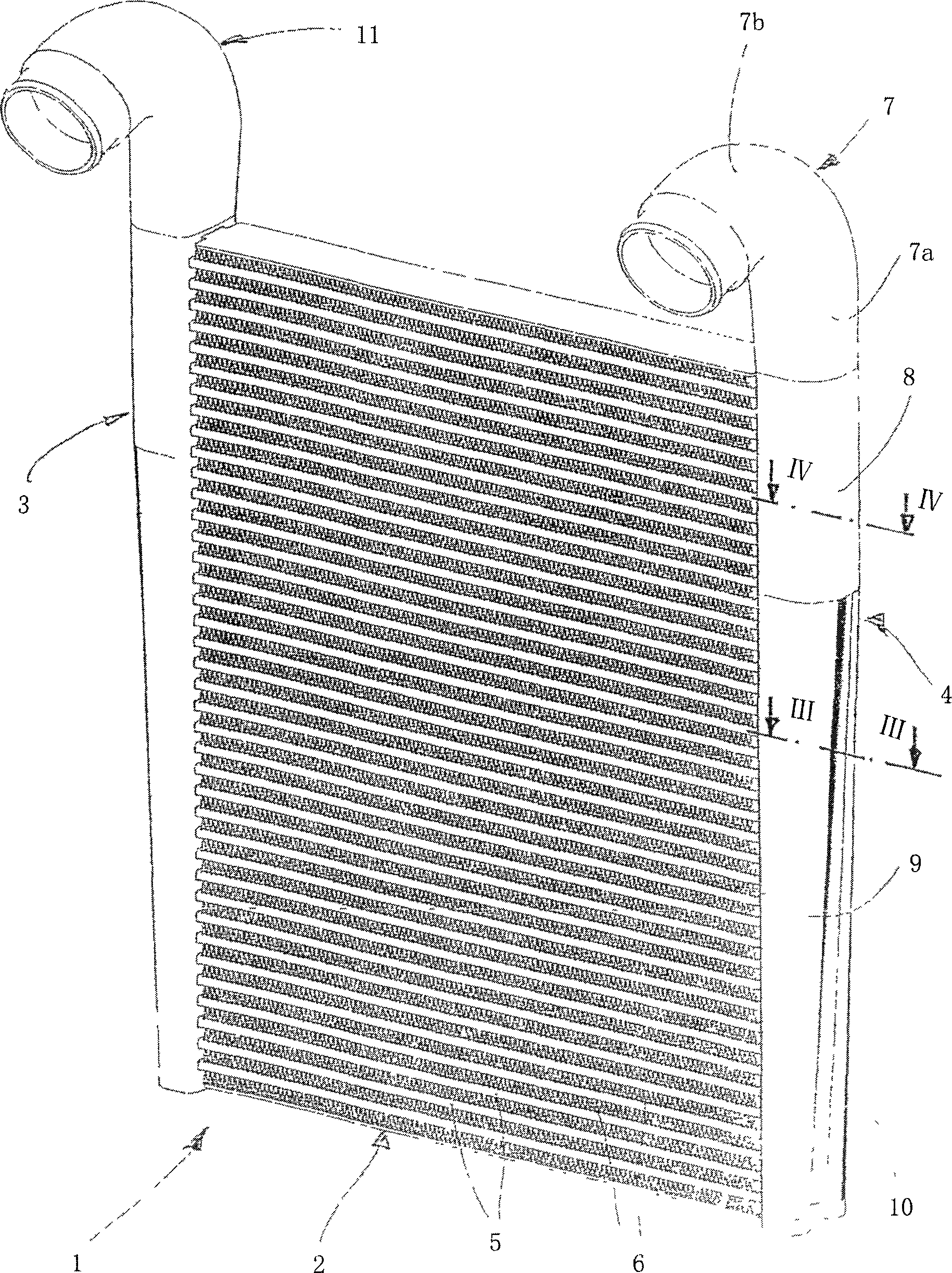
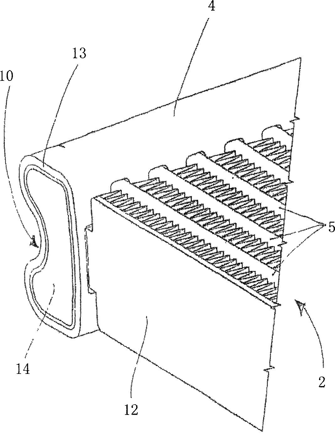
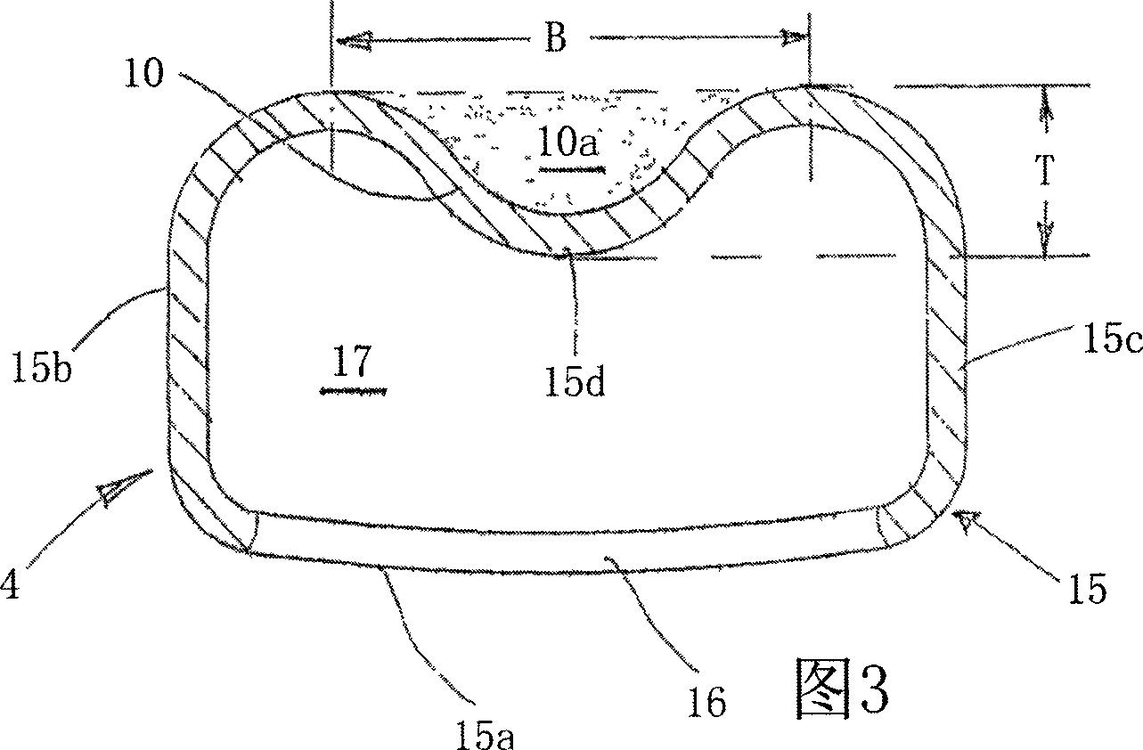
[0021] figure 1 In the figure is a charge air cooler 1 according to the invention, which consists of a heat exchanger core 2 and air boxes 3 , 4 arranged on both sides. The heat exchanger core 2 consists of flat tubes 5 and corrugated fins arranged between the flat tubes and through which ambient air flows. The tubes 5 lead into the air boxes 3 , 4 and are brazed together with them and the corrugated fins 6 . All parts such as tubes 5, wave fins 6 and air boxes 3, 4 are made of aluminum alloy. Each air box is a single whole and is divided into three sections (take air box 4 as an example), namely connecting pipe 7, cylindrical part 8 (non-cylindrical) and tapered or gradually flattened, with a The portion 9 of the longitudinal groove 10 extends in the longitudinal direction of the air box 4 . The connecting pipe 7 has a straight portion 7a completely centered and connected to the straight air box portion 8, and a bent portion 7b bent by about 90° to 120°. The air box 3 is ...


PUM

PropertyMeasurementUnit
Wall thicknessaaaaaaaaaa

Abstract

The invention relates to a heat exchanger for motor vehicles, especially for utility vehicles. Said heat exchanger comprises a heat exchanger unit (2), constituted of tubes (5) having tube ends and ribs (6) disposed between said tubes (5), and collecting tanks (3, 4), disposed on both ends and produced by internal high pressure forming for introducing and discharging a medium. Said collecting tanks (3, 4) comprise bottoms with openings for receiving the tube ends, covers and inlet and outlet tubes (7, 11).

Description

technical field [0001] The invention relates to a heat exchanger for a motor vehicle, in particular a charge air cooler for a commercial vehicle. Background technique [0002] Heat exchangers used in today's automobiles, such as charge air coolers, typically have a brazed heat exchanger core consisting of flat tubes, corrugated fins, and tube sheets to hold the tube ends. A collecting box, such as a so-called air box, is mounted on the tube sheet and is tightly connected to it. In commercial vehicles, the collecting box is often made of plastic and is mechanically connected to the tube sheet, eg a flared connection (Brdelverbindung), with rubber seals. Partial header boxes can also be made of cast aluminum boxes (Aluminiumgussksten) and welded together with tube sheets also made of aluminum. Charge air coolers with plastic air boxes are known from DE-A 199 53 785 and DE-A 199 53 787. In the foreseeable future development, the temperature of the charge air will reach a h...

Claims


Application Information

Patent Timeline
IPC IPC(8): F28F9/02F28F27/02
CPCF02B29/0456F28D2021/0082F28F9/02F28F9/0263F28F2009/029F28F2255/10Y02T10/12
Inventor 克劳斯·奥根施泰因卡斯滕·埃姆里希马丁·恩格尔哈特克劳斯·弗尔斯特佛朗哥·吉亚尼丹尼尔·亨德里克斯斯科特·赫罗欧赖因哈德·库尔安德烈·沙伊雷尔贝恩德·魏勒
Owner BEHR GMBH & CO KG
Why Eureka
Try Eureka