
Apparatus for covering the track joint (track joint cover) between the rotary plate and the bellows of a connection between two hinge-linked vehicle sections

a technology for connecting vehicles and bellows, which is applied in the direction of roofs, transportation items, transportation and packaging, etc., can solve the problems of compromising affecting the movability of the bellows, and putting a lot of pressure on the bellows

Active Publication Date: 2009-10-13
HUBNER GMBH
View PDF29 Cites 11 Cited by
  • Summary
  • Abstract
  • Description
  • Claims
  • Application Information

AI Technical Summary

Benefits of technology

The invention is about a device that covers the joint between two hinge-linked vehicle sections to prevent damage to the connection. The device allows for the track joint to move freely during all the potential traveling motions of the vehicle. The cover is attached to the bellows using clamping ledges that are fastened to the side wall of the bellows. The cover is also attached to the end frame of each vehicle section to ensure a secure connection. The cover is designed to protect the track joint from damage and vandalism. The invention also includes a bellows ceiling portion that is attached to the bellows side wall using clamping ledges and sheaths. Overall, the invention improves the durability and reliability of the track joint connection.

Problems solved by technology

This means that high demands are placed on the movability of the bellows.
It has now been found though that the movability of the bellows is quite restricted because of the track joint cover.
This is so inasmuch as the bellows is stabilized by the track joint cover, which has a box-shaped contour in cross section; this, as already explained, may strongly compromise the movability of the bellows as such.
As a result, the bellows material is subjected to considerable strains, this finally resulting in a reduced durability of the bellows as a whole.

Method used


Image

  • Apparatus for covering the track joint (track joint cover) between the rotary plate and the bellows of a connection between two hinge-linked vehicle sections
  • Apparatus for covering the track joint (track joint cover) between the rotary plate and the bellows of a connection between two hinge-linked vehicle sections
  • Apparatus for covering the track joint (track joint cover) between the rotary plate and the bellows of a connection between two hinge-linked vehicle sections

Examples


Embodiment Construction

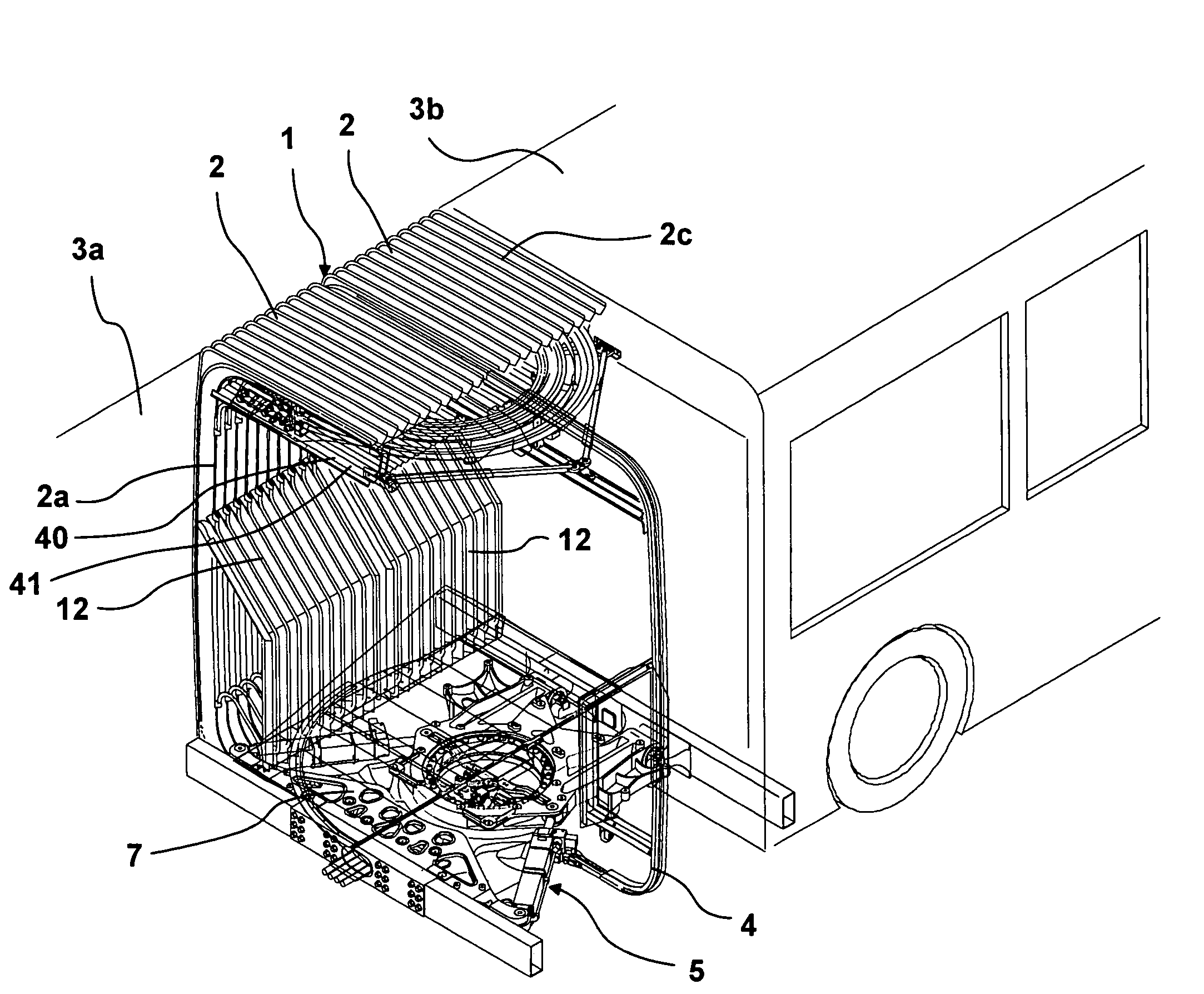
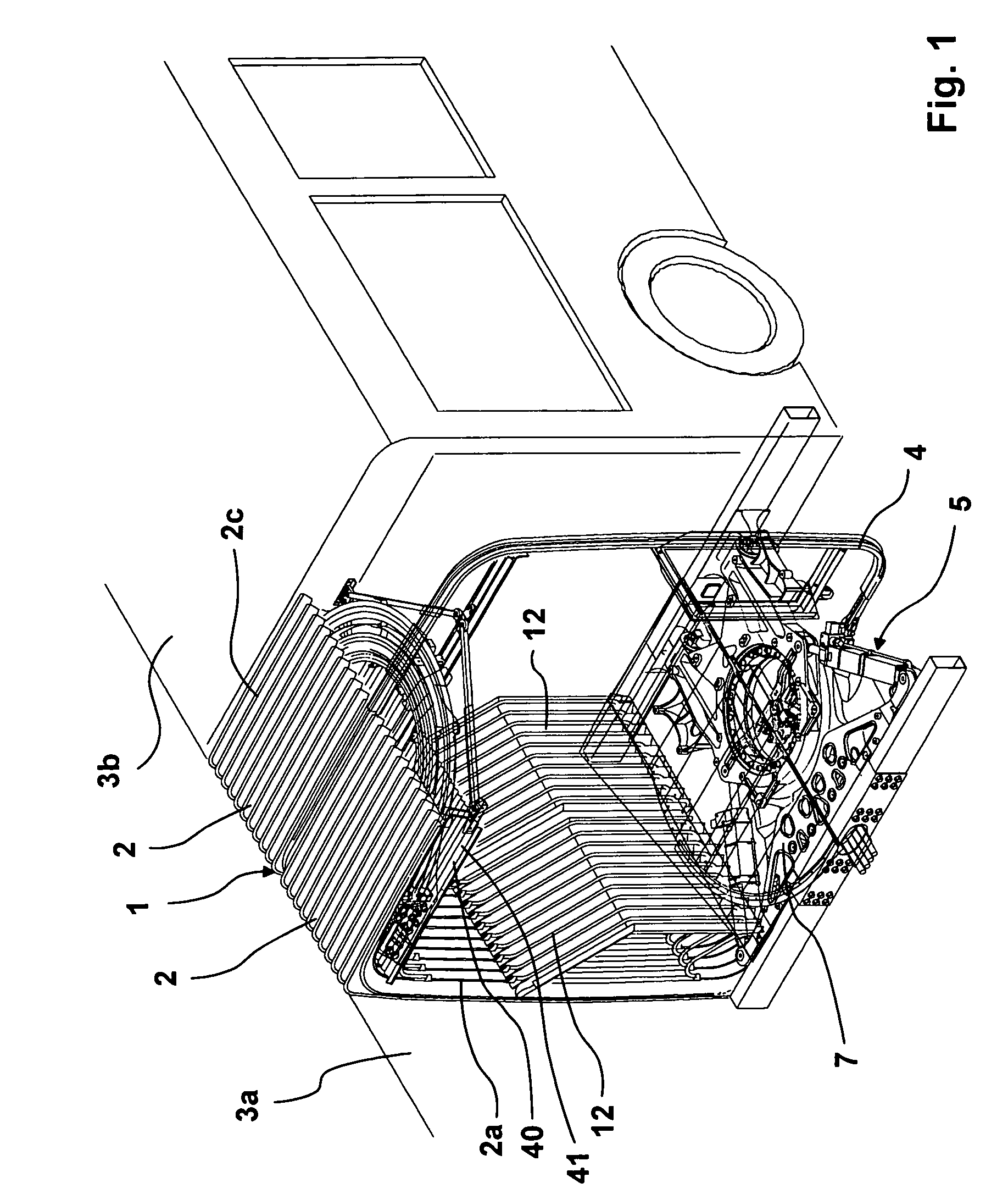
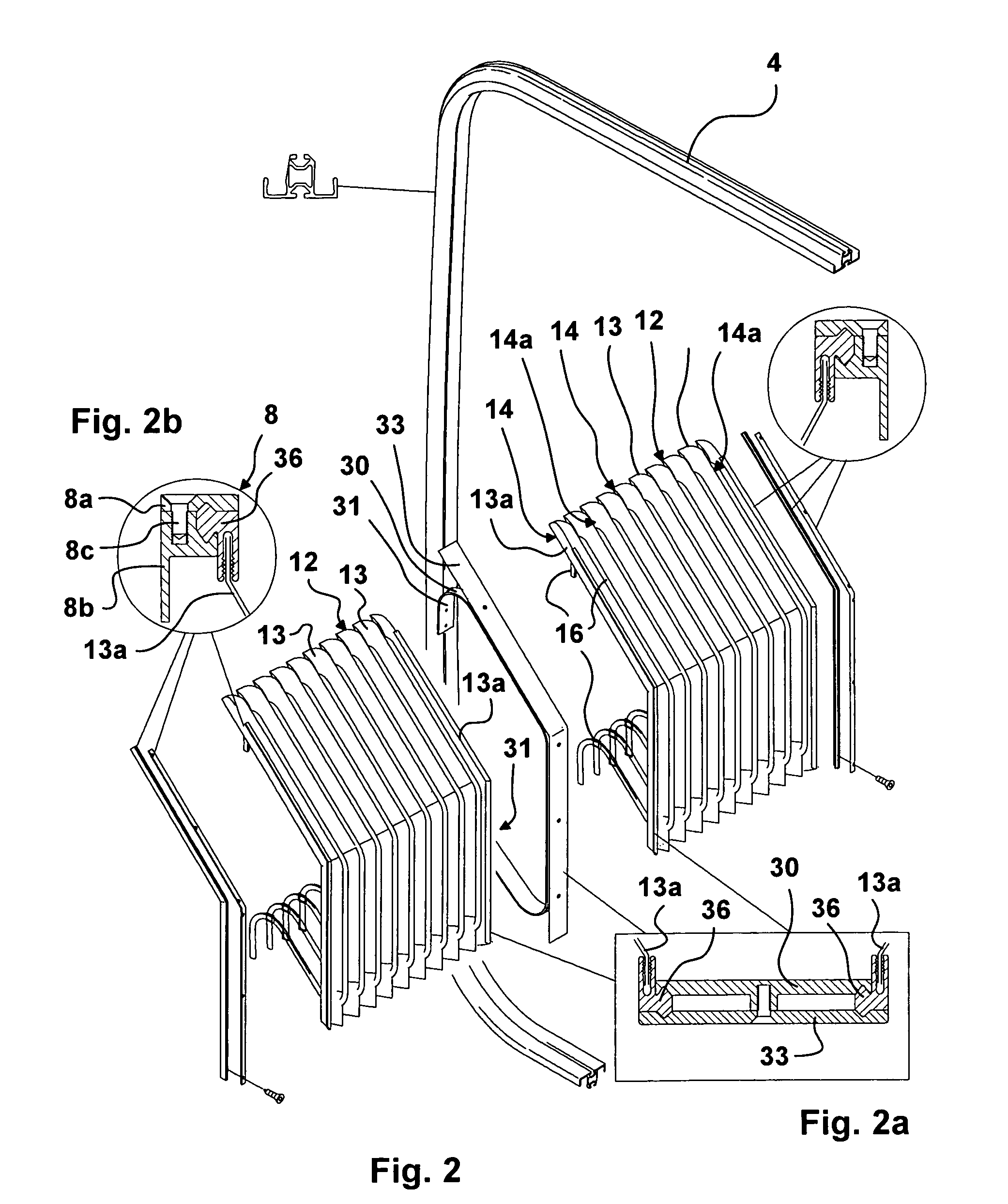
[0032]Referring to FIG. 1, the connection is indicated generally at 1. The connection is composed of the two identical bellows halves 2 that are joined together by the central frame 4. At their ends, the bellows halves are fastened to the vehicle parts 3a, 3b. In the region of the two bellows halves 2, there are located the two track joint covers 12 that cover the track joint between the bellows side wall 2a and the rotary plate or the vestibule plate 7. Such a track joint is located on either side of the bellows. Beneath the vestibule plate 7, there is the joint 5. The bellows with the bellows halves 2 is shaped to mate the end side contour of the vehicle sections and also surrounds the joint from the bottom. Consequently, the bellows has a box-shaped cross section. Beneath the bellows roof 2 and at a distance therefrom, there is located the bellows ceiling portion that covers the wiring located beneath the bellows roof.

[0033]The invention is directed to the way the track joint cov...


PUM


Abstract

The invention relates to an apparatus (12) for covering the track joint between the rotary plate (7) and the bellows of the connection (1) between two hinge-linked vehicle sections (3a, 3b), said bellows comprising two side walls (2a) that are joined together through a bellows roof (2c) at least, said track joint cover (12) having, like the bellows of said connection (1), singular corrugations or pleats (13), neighboring corrugations or pleats (13) being joined together by clamping ledges (16) in the region of their one apex at least, and the clamping ledges (16) being fastened at their one end at least to the side wall (2a) of the bellows (2) so as to be vertically movable.

Description

CROSS-REFERENCE TO RELATED APPLICATIONS[0001]This application claims Priority from German Application No. DE 10 2005 032 218.2-21 filed on 9, Jul. 2005[0002]1. Field of the Invention[0003]The invention relates to an apparatus for covering the track joint (track joint cover) between the rotary plate and the bellows of a connection between two hinge-linked vehicle sections, said bellows comprising two side walls that are joined together through a bellows roof at least, said track joint cover having, like the connection bellows, singular corrugations or pleats, neighboring corrugations or pleats being joined together by clamping ledges in the region of their one apex at least.[0004]2. Description of the Prior Art[0005]With articulated vehicles and here more specifically with articulated buses, tractor and trailer, meaning the two vehicle sections are coupled together through a joint, said joint having a rotary plate also referred to as a vestibule plate. Such a rotary plate makes it po...

Claims


Application Information

Patent Timeline
Patent Type & Authority Patents(United States)
IPC IPC(8): B62D63/00B60D5/00
CPCB60D5/003B62D47/025B61D17/22B60D5/006
Inventor KOCH, ROBERTMOSANER, KNUD
Owner HUBNER GMBH
Learn More