Dump truck

a dump truck and dump body technology, applied in the field of dump trucks, can solve the problems of large hydraulic systems, disadvantages in weight and cost, and time-efficient actuation of dump bodies, and achieve the effect of intensive cost and heavy construction

Active Publication Date: 2009-10-20
LIEBHERR MINING EQUIP
View PDF14 Cites 28 Cited by
  • Summary
  • Abstract
  • Description
  • Claims
  • Application Information

AI Technical Summary

Benefits of technology

[0004]Starting from this, it is the underlying object of the present invention to provide an improved dump truck of the named type which avoids disadvantages of the prior art and further develops the latter in an advantageous manner. A time-efficient unloading of the dump body should preferably be achieved without having to buy it at the cost of a design of the hydraulic system which is heavy in construction and intensive in cost.
[0006]It is therefore proposed not to use the hydraulic circuits of the dump truck fixedly for only one function and only to configure it therefor, but to use and operate them differently in dependence on the operating situation. By a selective combination and separate operation of the plurality of hydraulic circuits in dependence on the operating situation, the advantages of a plurality of separate hydraulic circuits can be maintained and simultaneously a fast actuation of the dump body can be achieved on unloading without a correspondingly large-dimensioned design of the corresponding hydraulic circuit. In accordance with the invention, the initially named first hydraulic circuit having the first pump device for the actuation of the dump body and the second hydraulic circuit having the second pump device for the actuation of the steering and / or of the brake of the dump truck chassis and / or of an accessory truck element are connected to one another by a valve device which is controlled by a control device such that, on the one hand, the two hydraulic circuits cooperate in an unloading mode and actuate the dump body together and, on the other hand, the two hydraulic circuits work separately in a travel mode so that the second hydraulic circuit is separated from the dump body and its actuator device. The performance of the two pump devices are added so-to-say by the combination of the two hydraulic circuits, whereby a fast unloading of the dump body can also be achieved despite the huge load. On the other hand, the valve device can uncouple the two hydraulic circuits from one another, whereby the second hydraulic circuit can be utilized specifically only for the steering and / or the braking device in the travel mode.
[0010]Advantageously, a further switching valve is provided parallel to the named flow control valve in the hydraulic circuit so that the hydraulic flow acting on the actuator device of the dump body can be controlled both by means of the flow control valve and by means of the further switching valve. This can in particular be utilized for a sequential control of the said flow control and switching valves and the hydraulic flow amount controlled thereby, in particular to the effect that, on a desired slow positional movement of the dump body, the hydraulic flow is controlled via the flow control valve and, on a desired fast positional movement of the dump body, the flow control valve and its flow resistance is bypassed by enabling the switching valves provided in parallel. Small hydraulic volumes can thereby be controlled precisely by the flow control valve, whereas, on the other hand, large positional speeds are made possible via the additional switching valve.
[0012]In connection with the aforesaid switch and flow control valves, the adjustment path of the dump body can thereby be finely controlled by a combination of valve actuation and variable delivery pump actuation and a desired speed profile can be generated.

Problems solved by technology

Such large hydraulic systems are, however, disadvantageous with respect to their weight and the costs.
If, in contrast, hydraulic systems of smaller dimensions are used for the actuation of the dump body, the weight and costs can admittedly be reduced, but disadvantages arise with respect to a time-efficient actuation of the dump body.

Method used


Image

  • Dump truck
  • Dump truck
  • Dump truck

Examples


Embodiment Construction

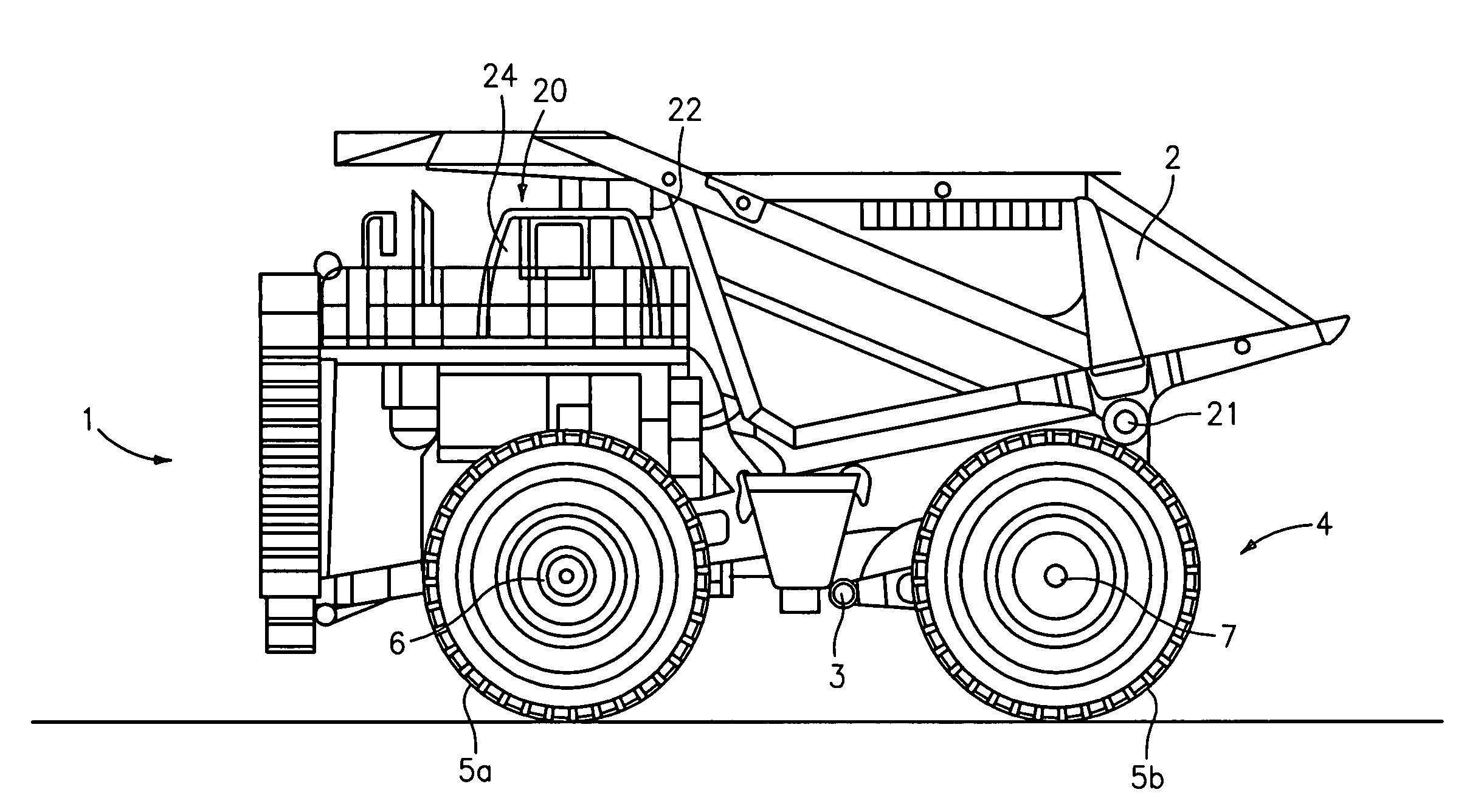
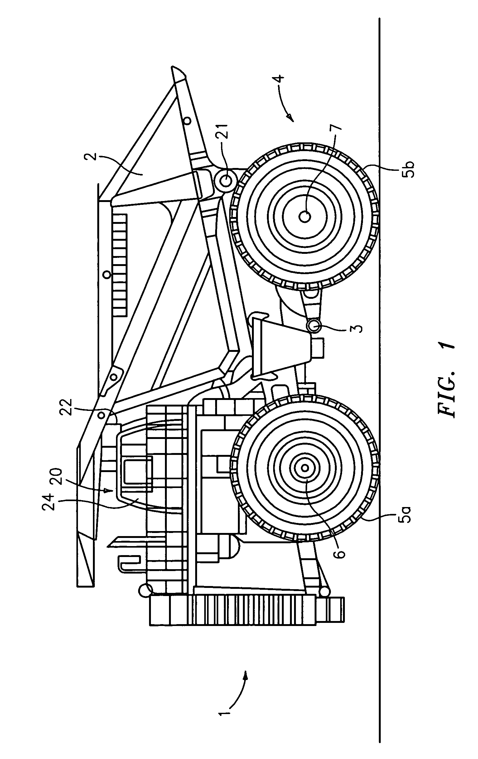
[0020]The large dump truck 1 shown in the drawing includes a dump body 2 which is supported on a frame 3 which is supported on the ground via a chassis 4. As FIG. 1 shows, an operator's compartment 20 is seated on the frame 3 in a manner known per se and extends above the front wheels 5a of the chassis 4. More than two rear wheels 5b, for example four rear wheels 5b, are provided at the rear axle of the chassis 4 which are advantageously driven separately by individual wheel drives. The large dump truck can typically have a length of over ten meters and a wheel diameter of over three meters and can receive bulk material loads in the range of several 100 metric tons.

[0021]The wheels 5 can be braked by a braking device 7 which may be a hydraulic braking device working hydraulically or assisted hydraulically. It is nevertheless within the scope of the invention that, in the alternative to or in addition to hydraulic brakes, the truck 1 is provided with other types of brakes, in particu...


PUM


Abstract

The present invention relates to a dump truck or large mining truck, comprising a dump body for the transport of overburden or the like, a first hydraulic circuit having a first pump device for the actuation of the dump body as well as a second hydraulic circuit having a second pump device for the actuation of a steering and / or of a braking device of the dumper truck chassis and / or an auxiliary truck element. In accordance with the invention, the first, second and / or a further hydraulic circuit having are connected to one another by a valve device which is controlled by a control device such that the plurality of hydraulic circuits cooperate in an unloading mode and actuate the dump body together and, on the other hand, the hydraulic circuits work separately in a travel mode so that the second hydraulic circuit and / or any further hydraulic circuit is separated from the dump body and its actuator device. The performance of the pump devices are added so-to-say by the combination of the hydraulic circuits, whereby a fast unloading of the dump body can be achieved despite the huge load. On the other hand, the valve device can uncouple the hydraulic circuits from one another, whereby the second hydraulic circuit can be utilized specifically only for the steering and / or the braking device in the travel mode.

Description

BACKGROUND OF THE INVENTION[0001]The present invention relates to a dump truck, in particular to a so-called large mining truck, comprising a dump body for the transport of overburden or the like, a first hydraulic circuit having a first pump device for the actuation of the dump body as well as a second hydraulic circuit having a second pump device for the actuation of a steering and / or of a braking device of the dumper truck chassis and / or an auxiliary truck element.[0002]Such a large mining truck or large dump truck is described, for example, in EP 1 359 032. Such large dump trucks are predominantly used in mining operations for the transport of the mined minerals and ores, with the bulk material dump trucks being manufactured in a size of several 100 metric tons unladen weight and working load. WO 92 / 04196 also shows such a large dump truck.[0003]As a rule, in such large dump trucks, hydraulic circuits are used for the actuation of the steering, the brakes, the dump body as well ...

Claims


Application Information

Patent Timeline
Patent Type & Authority Patents(United States)
IPC IPC(8): B60P1/16
CPCB60W10/184B60W10/20B60W10/30F15B11/17B60W30/18054F15B2211/265F15B2211/20546F15B2211/20576
Inventor WHITFIELD, JR., JAMES ARTHURYATES, MICHAEL KELLY
Owner LIEBHERR MINING EQUIP
Why Eureka
Try Eureka