Semi-autonomous central supply system for passenger seats

a central supply system and semi-autonomous technology, applied in the direction of cell components, electrochemical generators, cell component details, etc., can solve the problems of less efficient processing, achieve the effect of preventing the risk of oxyhydrogen gas reaction, facilitating rapid flow of hydrogen, and increasing safety on board the aircra

Inactive Publication Date: 2011-10-11
AIRBUS OPERATIONS GMBH
View PDF8 Cites 2 Cited by
  • Summary
  • Abstract
  • Description
  • Claims
  • Application Information

AI Technical Summary

Benefits of technology

[0014]The system allows for creation of an autonomous consumer element that can be supplied with energy in an autarkic fashion by means of a fuel cell element and a rechargeable metal hydride storage cell. In contrast to an hydrogen supply from a central hydrogen tank, in which a complex pipeline system transports the hydrogen to the fuel cells, the fuel cell system with a decentralized, rechargeable metal hydride storage cell need not utilize such a pipeline system. The position of the consumer elements can be flexibly changed without interrupting the hydrogen supply. In a central hydrogen supply, the hydrogen lines from the central hydrogen tank with the consumer element also need to be routed through the cabin and are constantly filled with hydrogen and therefore under pressure such that leaks could develop at the interfaces and hydrogen could escape into the aircraft and form oxyhydrogen gas in case of a crack or fracture. Consequently, the hydrogen supply lines need to feature dependable safety devices such as, for example, a double-walled pipe construction with an inner pipe and an outer pipe. In one example of a rechargeable and decentralized metal hydride storage cell for fuel cells, the hydrogen supply lines are pressurized only during a charging process, i.e., for a defined period of time. In addition, the charging process may take place only under controlled conditions, i.e., when the passengers are not on board. Thus, the safety requirements may be much less costly, eliminating heavy double-walled construction of the piping, for example, while further lowering the risk for the passengers in an aircraft. Furthermore, the service intervals may be extended and inspection and replacement of equipment for the recharging device may be made much easier and less frequent.
[0027]In another example, the system includes a control unit. The control unit is designed for controlling the ventilation valve element, the aeration valve element and the filling valve element. The individual valve elements do not have to be opened and closed manually, but rather may be centrally opened and closed by the control unit. The control unit may control the entire filling process. The control unit may initially ventilate the hydrogen supply line by opening the filling valve element as well as the ventilation valve element after all filling hoses are connected, i.e., after connecting the hydrogen source to the filling valve element and after connecting an air source to the air connection of the aeration valve element. This causes hydrogen to flow into the hydrogen supply line and to displace the air situated therein. The control unit closes the ventilation valve element after a defined time interval or after the hydrogen concentration in the hydrogen supply line is measured with the aid of sensors such that the pressure of the hydrogen situated in the line increases. The rechargeable metal hydride storage begins to fill due to the pressure being built up until it is completely charged with hydrogen. After a defined time interval, it is ensured that all metal hydride storages are filled such that the hydrogen filling valve is closed. The hydrogen remaining in the hydrogen supply line can subsequently be blown out with air by opening the ventilation valve element and the aeration valve element. The control unit is able to automatically and independently control this charging process such that a quick and reliable charging process of the rechargeable metal hydride storage is realized.

Problems solved by technology

Consequently, leaks and cracks could develop at their interfaces such that hydrogen would be able to escape into the cabin and lead to an oxyhydrogen reaction.
However, the need for exchange makes the process less efficient.

Method used


Image

  • Semi-autonomous central supply system for passenger seats
  • Semi-autonomous central supply system for passenger seats
  • Semi-autonomous central supply system for passenger seats

Examples


Embodiment Construction

[0034]The example described and drawings rendered are illustrative and are not to be read as limiting the scope of the invention as it is defined by the appended claims. Identical or similar components in different figures are identified by the same reference symbols. The figures show schematic representations that are not drawn true-to-scale.

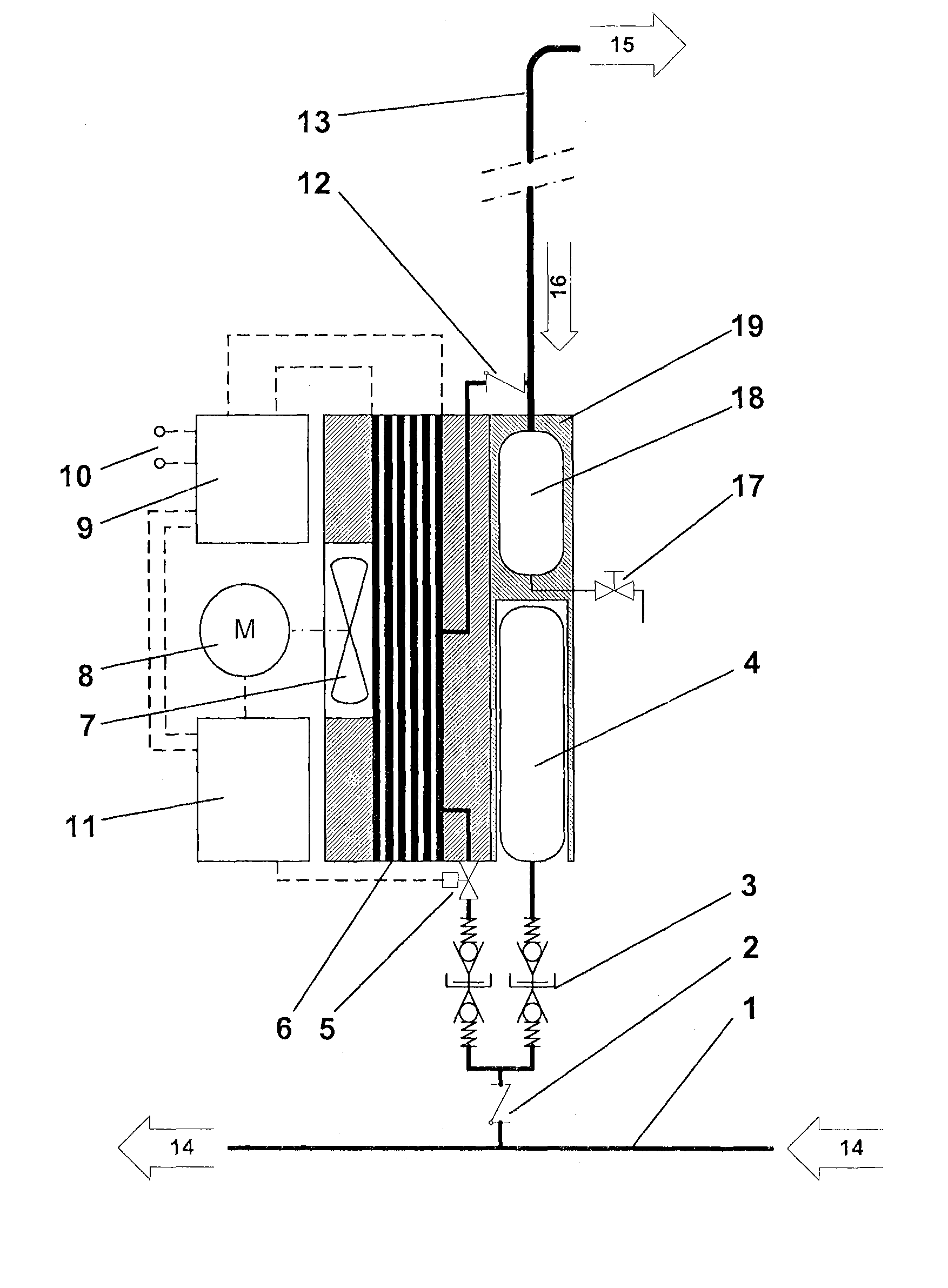
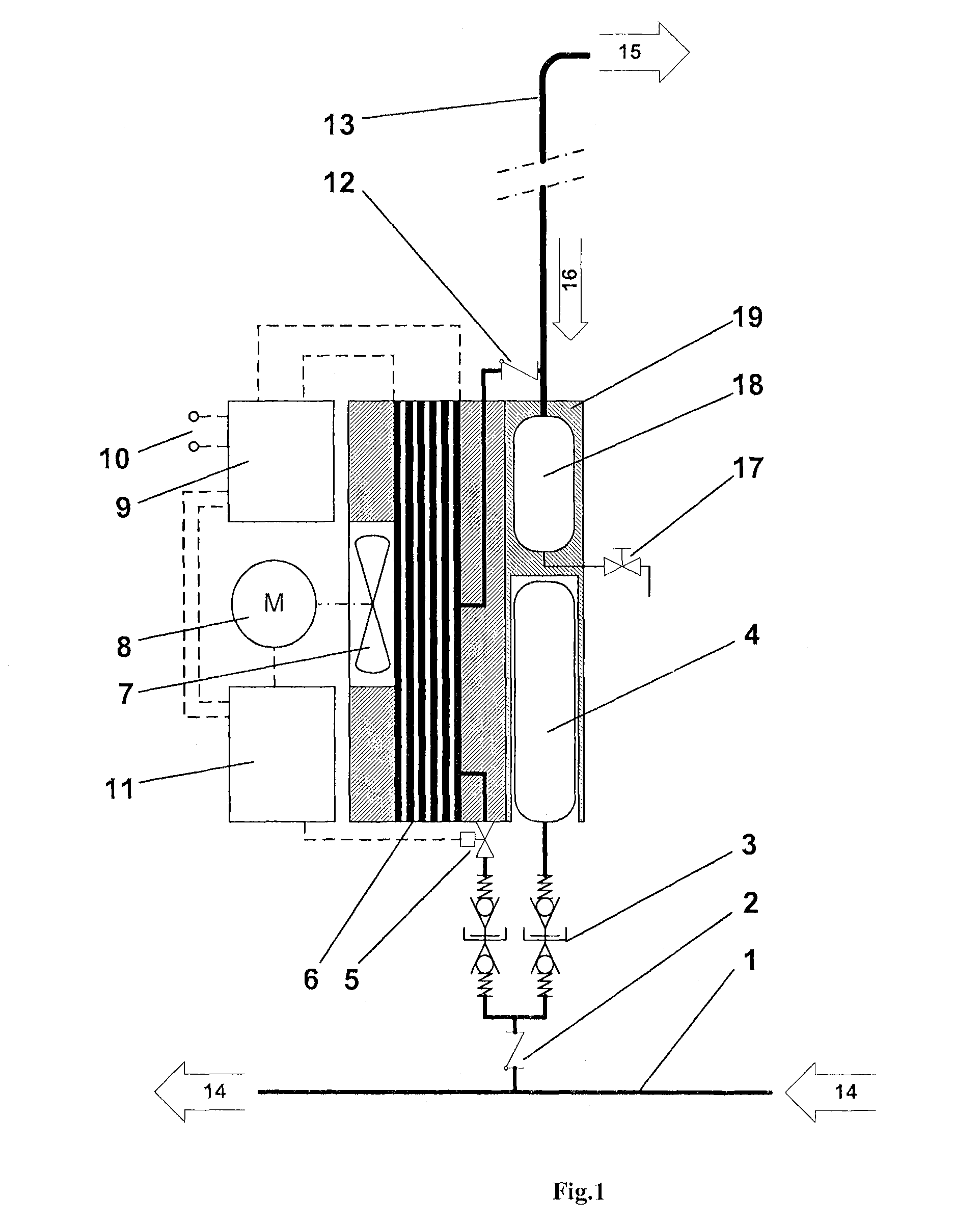
[0035]FIG. 1 shows an embodiment of the system for generating energy for a consumer element 20 in an aircraft. FIG. 1 shows a fuel cell element 6 and a rechargeable metal hydride storage cell 4. The rechargeable metal hydride storage cell 4 is designed for supplying the fuel cell element 6 with hydrogen. In this case, the rechargeable metal hydride storage cell 4 is designed in such a way that it can be charged with hydrogen.

[0036]FIG. 1 furthermore shows an embodiment of the system, in which the exchangeable metal hydride storage cell 4 and a collection container 18 are arranged in a separate component or carrier module 19. The carrier module ...


PUM

PropertyMeasurementUnit
energyaaaaaaaaaa
thermal energyaaaaaaaaaa
electric energyaaaaaaaaaa

Abstract

A system for generating energy for a consumer element in an aircraft includes the consumer element with a fuel cell element and a rechargeable metal hydride storage cell. The rechargeable metal hydride storage cell is designed for supplying the fuel cell element with hydrogen such that energy can be generated for the consumer element. The rechargeable metal hydride storage cell is furthermore designed in such a way that it can be charged with hydrogen.

Description

REFERENCE TO RELATED APPLICATIONS[0001]This application claims the benefit of the filing date of U.S. Provisional Patent Application No. 60 / 821,735 filed Aug. 8, 2006 and of German Patent Application No. 10 2006 037 054.6 filed Aug. 8, 2006, the disclosures of which are hereby incorporated herein by reference.FIELD OF THE INVENTION[0002]The field pertains to a device and a method for charging a rechargeable metal hydride storage cell, as well as to a system for supplying a consumer element with energy in an aircraft.BACKGROUND OF THE INVENTION[0003]In commercial aircraft, many modules perform more and more secondary tasks in addition to their original function. For example, passenger seats not only provide a high seating comfort and safety standard, but also fulfill secondary functions such as communication and entertainment functions, in certain instances, even enhanced comfort functions such as electric seat adjustments or massage functions.[0004]In order to meet the energy demand...

Claims


Application Information

Patent Timeline
Patent Type & Authority Patents(United States)
IPC IPC(8): H01M8/00H01M8/02H01M8/06B64D11/00B64D27/00B64D37/00
CPCH01M8/04007H01M8/04208H01M8/04216H01M8/04231H01M8/065Y02E60/50
Inventor HOFFJANN, CLAUSSCHULDZIG, HANSGEORG
Owner AIRBUS OPERATIONS GMBH
Why Eureka
Try Eureka