Variable compression ratio engine

a compression ratio and variable technology, applied in the direction of engines, machines/engines, mechanical equipment, etc., can solve the problems of inability to achieve tight machining tolerances, inability to manufacture and assembly tolerances, and inability to manufacture large crankcases, etc., to achieve low cost, high reliability, and small size

Active Publication Date: 2015-04-09
MENDLER EDWARD CHARLES
View PDF4 Cites 2 Cited by
  • Summary
  • Abstract
  • Description
  • Claims
  • Application Information

AI Technical Summary

Benefits of technology

[0011]The engine includes a seal for sealing between the crankcase assembly and the cylinder head assembly. A garter seal or other type of seal may be used that preferably slides along the same surface or bearing race on the cylinder head assembly as the bushing. Advantages of the sealing system of the present invention include low cost, high reliability and noise containment.
[0012]A significant benefit of the variable compression ratio mechanism of the present invention is its small size and light weight. The control shaft is mounted between the valve stems and close to the combustion chamber roof, near the top of the cylinder. The location of the control shaft near to the top of the cylinder is beneficial for the stoutness and stiffness of the variable compression ratio mechanism, while also providing a compact and light weight engine. A control shaft having a removable bearing and a fluted shaft may optionally be used to locate the control shaft as near as practical to the top of the cylinder. There is no link between the cylinder head assembly and control shaft to compromise the location of the control shaft or mandate a large heavy cylinder head construction.
[0013]The variable compression ratio mechanism of the present invention may be practiced in a number of different engine configurations, including in-line engines, V-engines and horizontally opposed piston engines. In an embodiment of the present invention, the engine has only two cylinders, and has a generally horizontally opposed piston layout, commonly referred to as a Boxer engine layout. According to the present invention, the control shafts in the Boxer engine are short and sturdy, and have only one pair of primary control shaft bearings and only one pair of eccentric bearings, resulting in easily attainable machining and assembly tolerances, low manufacturing cost, and a sturdy, compact light-weight variable compression ratio engine. Preferably the crankcase has a clamshell construction where a front half of the crankcase slides onto the front end of the crankshaft, and a rear half of the crankcase slides onto the rear half of the crankshaft, with the two halves bolted together to form a low cost sturdy crankcase construction. Preferably the front and rear crankcase halves include armatures that capture and house the primary control shaft bearings, making for a light weight very low cost crankcase construction.

Problems solved by technology

Machining and assembly tolerances are a problem with the variable compression ratio mechanism taught by Gillbrand.
Additionally, the shafts must remain true when the engine is running and exposed to high mechanical loads.
Attaining precision alignment of the shafts can be attained, however, an undesirably massive crankcase is needed, and attaining tight machining tolerances is relatively costly.
The engine has many links and hinge joints which also adds to manufacturing and alignment costs.
Another problem with the engine is that hinge shaft (20) is located relatively far from crankshaft (6) and the centerline axis of cylinder (10) in order to minimize the degree of tipping required to change compression ratio.
The high moment forces further increase the need for an undesirably massive and heavy crankcase.
An in-line engine layout is employed to minimize weight and complexity, however the crankcase is still massive.
Another problem with the engine is noise and vibration because of the high crankcase walls (24) that are not anchored at their top, and the large gasket (44) which does not contain noise within the crankcase.
However, a problem with the engine is that a massive and large cylinder head is needed to accommodate the links and control shaft in the cylinder head.
An in-line engine layout is employed to minimize weight and complexity, however the crankcase is still massive.
The engine has a relatively tall engine height which will make packaging in some automobiles impractical.
Another problem with the engine is that there are a large number of eccentric bearings and links, which increases manufacturing and alignment cost.
A problem with the variable compression ratio mechanism shown in U.S. Pat. No. 7,047,917 is that precision alignment of the two control shafts is required for durable operation of the engine, and attaining the precision alignment is costly.
A second problem with the engine is that there are a large number of eccentric bearings, which increases manufacturing and alignment cost.
An in-line engine layout is employed to minimize weight and complexity, however the crankcase is still relatively massive.

Method used


Image

  • Variable compression ratio engine
  • Variable compression ratio engine
  • Variable compression ratio engine

Examples


Embodiment Construction

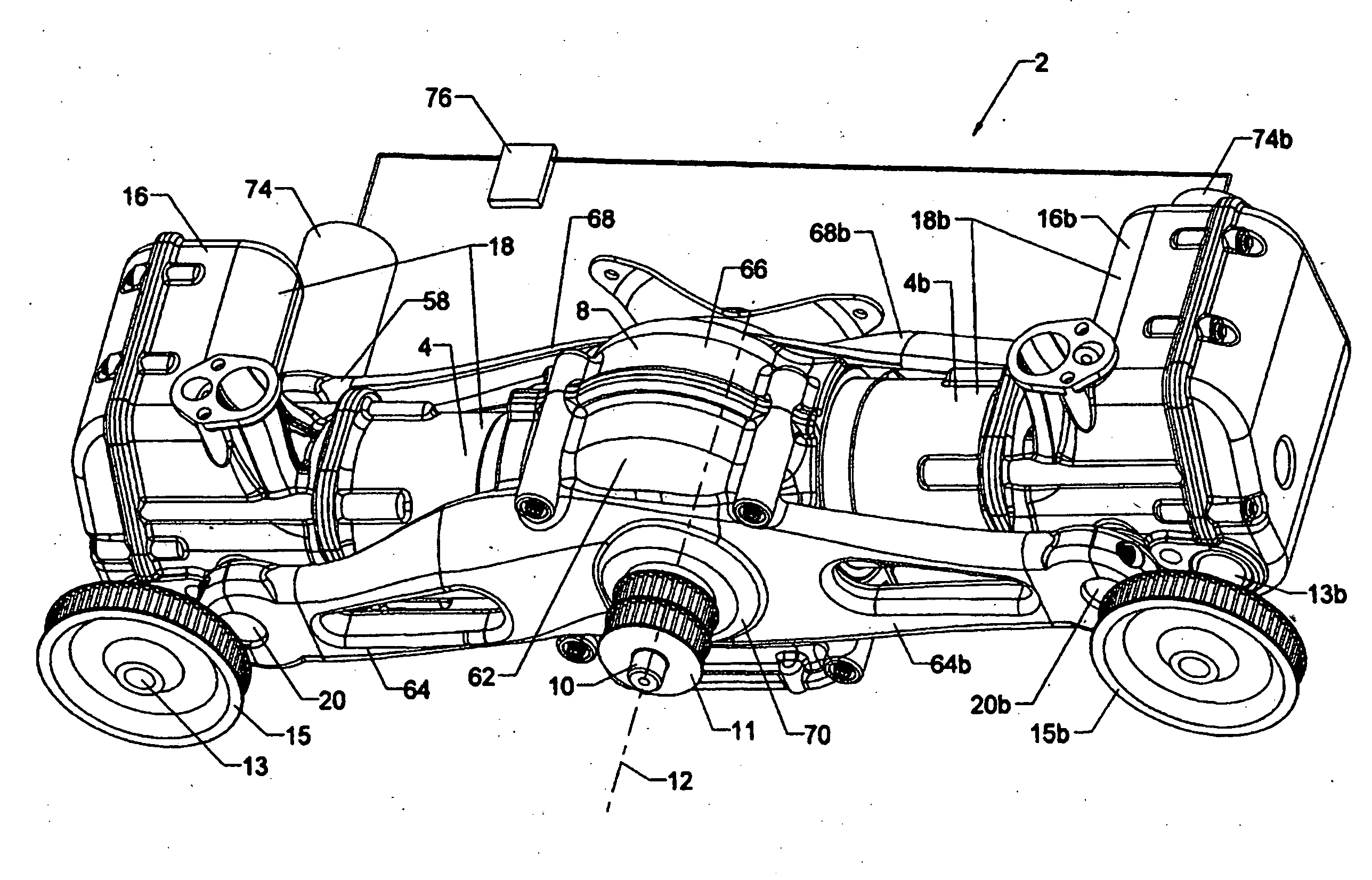
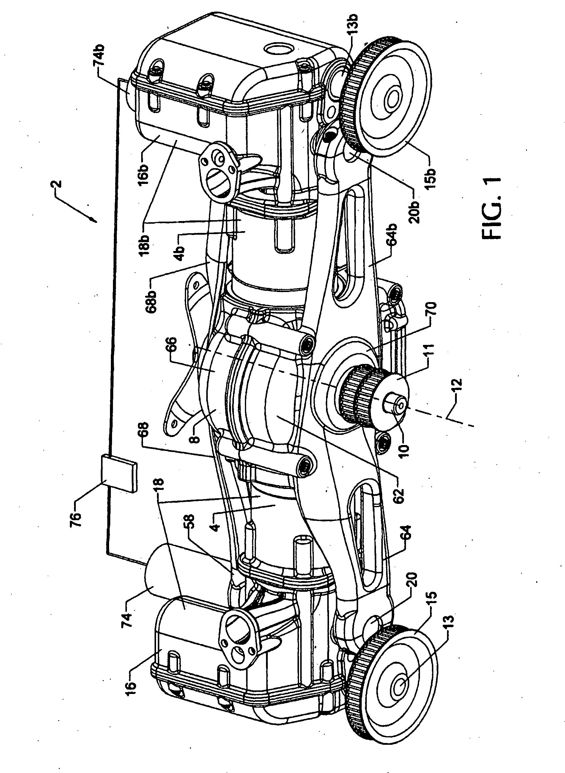
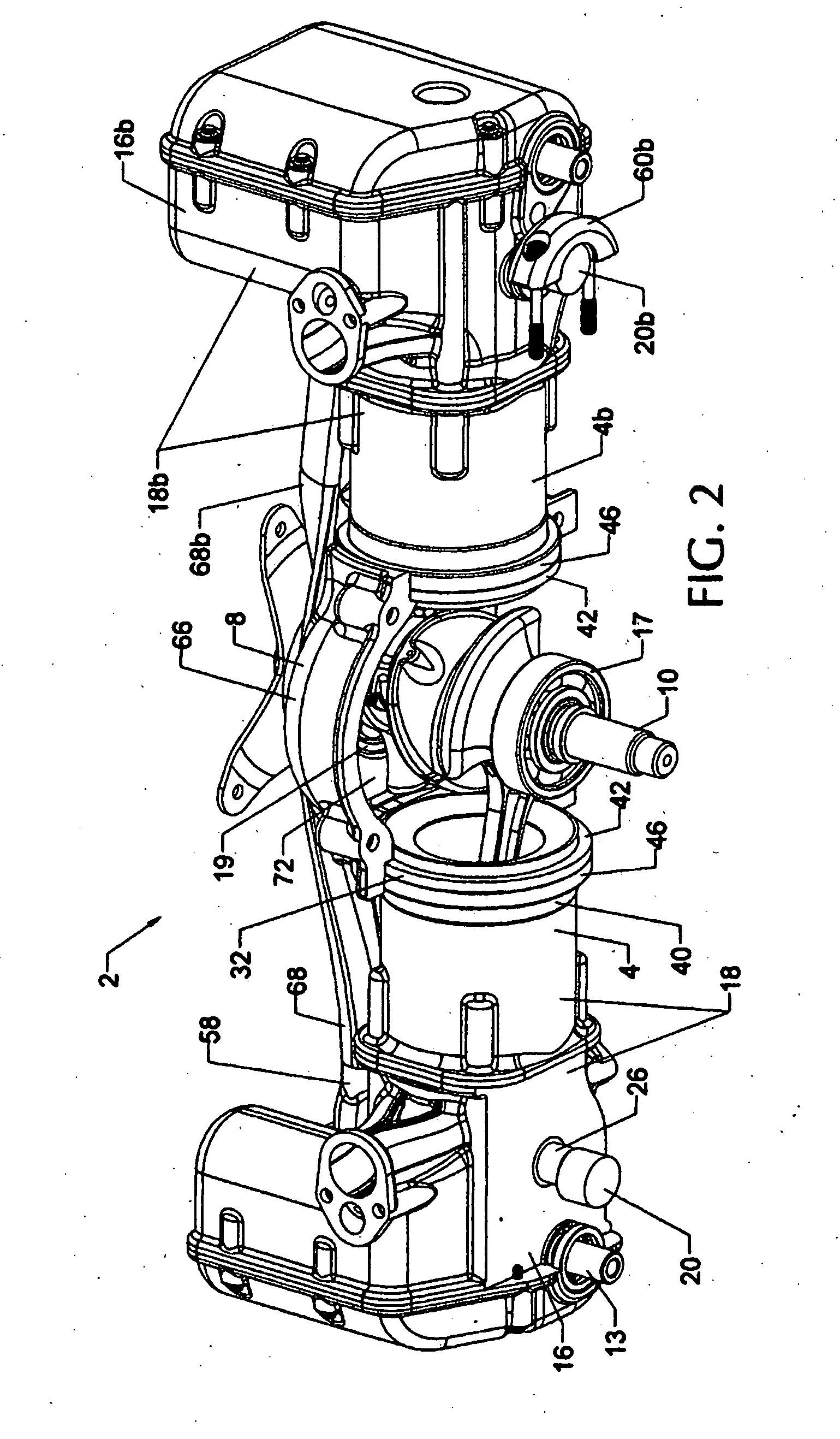
[0022]FIGS. 1, 2 and 3 are intended to illustrate an engine 2 having a variable compression ratio mechanism according to the present invention. FIGS. 2 is similar to FIG. 1, but shows a portion of the crankcase and cylinder head removed to show the variable compression ratio mechanism in greater detail. Engine 2 has at least one cylinder 4. FIG. 3 is similar to FIG. 2, but shows a portion of cylinder 4 cut away to better show the variable compression ratio mechanism of the present invention. The cylinder head casting is also hidden to better show the variable compression ratio mechanism.

[0023]Engine 2 has a piston 6 mounted for reciprocating movement in cylinder 4, and a crankcase assembly 8. A crankshaft 10 is rotatably mounted in crankcase 8, crankshaft 10 defining a crankshaft axis 12 about which crankshaft 10 rotates in crankcase 8. Engine 2 has at least one connecting rod 14 connecting piston 6 to crankshaft 10. Engine 2 also has a cylinder head 16 for sealing cylinder 4, and a...


PUM


Abstract

According to the present invention, a variable compression ratio engine includes a cylinder head and crankcase directly joined by a control shaft, thereby eliminating use of a link between the control shaft and cylinder head. The present invention has a low manufacturing cost and a small size ideal for mass production applications. In the preferred embodiment of the present invention, the control shaft includes a primary set of bearings and an eccentric set of bearings. The primary control shaft set of bearings are mounted directly in the crankcase assembly, and the eccentric control shaft bearings are mounted directly in the cylinder head assembly. There is only one control shaft per cylinder head, and there is no link between the control shaft and cylinder head assembly. The variable compression ratio mechanism also includes moment retaining means to prevent the cylinder head assembly from rotating out of alignment when the engine is running. The moment retaining means is a bushing that is mounted around the engine cylinder. The bushing provides the moment retaining means needed for holding the cylinder head assembly in alignment when the engine is running, and also provides displacement means, where the cylinder head assembly can slide on the bushing. The displacement means is needed to allow the cylinder head assembly to move relative to the crankcase when compression ratio is adjusted.

Description

[0001]This application relates to Provisional Application No. 61 / 633,402 having a filing date of Feb. 9, 2012.BACKGROUND OF THE INVENTION[0002]Variable compression ratio can significantly increase the fuel efficiency of reciprocating piston internal combustion engines used in passenger cars, light duty trucks and other vehicles. The present invention relates to a variable compression ratio mechanism having an eccentric control shaft for adjusting engine compression ratio.[0003]An engine having an eccentric control shaft is shown by Per Gillbrand in U.S. Pat. Nos. 5,611,301 and 5,562,069. Referring to U.S. Pat. No. 5,562,069, a crankcase (4) is connected to a cylinder head assembly (2) with a hinge shaft (20). Use of the hinge shaft (20) enables the cylinder head assembly (2) to tip relative to the crankcase (4) for adjusting compression ratio. A control shaft (56) is also mounted in a crankcase (4). The engine has only one control shaft (56) per cylinder head assembly (2). The engin...

Claims


Application Information

Patent Timeline
Patent Type & Authority Applications(United States)
IPC IPC(8): F02B75/04
CPCF02B75/047F02B75/041F02D15/04F02D15/00
Inventor MENDLER, EDWARD CHARLES
Owner MENDLER EDWARD CHARLES
Why Eureka
Try Eureka