Stationary coil oscillator scanning system

a scanning system and torsion oscillator technology, applied in the field of scanning systems, can solve the problems of inability to use scanning devices such as commercial or desktop laser printers, inferior to rotating mirror devices, material bulk, etc., and achieve the effects of improving performance, small size, and lack of expens

Inactive Publication Date: 2005-02-10
LEXMARK INT INC
View PDF3 Cites 11 Cited by
  • Summary
  • Abstract
  • Description
  • Claims
  • Application Information

AI Technical Summary

Benefits of technology

[0003] Contrary to current conventional wisdom, it has been discovered that torsion oscillators are actually superior devices for use in some scanning devices such as desktop laser printers. One of the advantages of the torsion oscillator is its small size and lack of expense. The solutions to problems with torsion oscillators involve both improved techniques for controlling the torsion oscillator and adapting the scanning apparatus to accommodate the torsion oscillator. After the adoption of improved control or adaptation techniques, the torsion oscillator offers improved performance at the same price or equivalent performance at a reduced expense compared to competing technologies. The present invention is instrumental in moving the torsion oscillator from the unacceptable category to the preferred category for many scanning applications. When appropriately constructed, the advantages of the torsion oscillator scanner as described herein, as compared to rotating mirror devices, include improved thermal characteristics, faster times to first print, reduced noise, and easier and less expensive optical design.
[0004] The preferred embodiment provides a torsion oscillator scanner with magnets on moving parts and it includes a stationary coil. The advantages of a stationary coil include a reduced variation in scan frequency, and increased robustness because it is practical to use heavy conductors and simple lithography. A large window of operating frequencies is practical due to ease of operation in off-resonance frequency conditions because the drive current to the coil may be large because of the heavy construction of the coil. In addition, this construction is less sensitive to wandering operational frequencies that result from changes in the drive frequency. Again, because of the drive current handling capability, improved time to first print is achieved. In addition, because of a better mirror to scanner size ratio, operational advantages may be achieved such as improved laser spot size or smaller size mirrors. Finally, because of the simplified mirror construction, there is little tendency for patterning on the mirror such as might be experienced if coils were placed on or below the mirror, which may cause patterns to form.
[0006] Heating a torsion spring causes little or no material degradation, but it does change the resonant frequency of the spring. In turn, the change in resonant frequency changes the oscillation characteristics of the galvanometric oscillator. As the spring increases in temperature, the resonant frequency drops and typically drifts away from the drive frequency, which is the frequency at which the oscillator is being driven and is the frequency at which it does oscillate. Since the oscillator is operating at the drive frequency removed from the resonant frequency, more energy is required to maintain the correct amplitude and speed of oscillation, or the amplitude and speed of oscillation will decrease. In the present invention, the coil is placed near the plate and is thermally isolated or removed from the torsion springs so that the coil provides little to no heating of the torsion spring. A permanent magnet is placed on the oscillating object for interacting with an oscillating or alternating magnetic field produced by the nearby coil. In this manner, the seemingly insignificant problem of heating the torsion springs is overcome.
[0007] In accordance with one embodiment, a torsion oscillator as described above includes a plate member preferably having a non rectangular shape. For example, the plate member may be elliptical, oval, racetrack, or circular in shape and it has an upper and lower surface and rotates about a rotational axis. A frame is disposed adjacent the plate member in a spaced apart relation and is preferably supporting the plate member through torsion springs. A reflective surface is formed on the plate, and at least one magnet is disposed on the plate. A coil is located on the frame and is configured for inducing the electromagnetic force on the magnet. Alternating current is applied to the coil to oscillate the plate and the reflective surface through a rotational angle of oscillation at an oscillation frequency and will scan the plate through a scan path. Likewise, the view of the reflective surface will be scanned through a corresponding scan path. In the preferred embodiment, the plate, the frame and the torsion springs all made of silicon and the plate as an arrow dynamic streamlined configuration to minimize when the resistance and air flow interference effects. Also, in the preferred embodiment, a light source produces a light beam and directs the light beam onto the reflective surface so that it is scanned through the scan path.

Problems solved by technology

Problems associated with torsion oscillators include bulk associated with the materials used for the springs, magnets and coils; frequency drift; and instability.
Current conventional wisdom provides that torsion oscillators are inferior to rotating mirror devices and are unacceptable for use in scanning devices such as commercial or desktop laser printers.
In the typical galvanometric oscillators of past, coils were placed in the oscillating object For small, silicon based, galvanometric oscillators, this structure has found has been found especially problematic.
When a coil is located in the oscillating object, such as a plate, it produces what appears to be a fairly minor amount of heat, which typically is insufficient to cause electrical or material breakdown problems.
These are the typical problems associated with heat in galvanometric oscillators.
While the temperature change in the torsion springs would ordinarily be considered insignificant and would be overlooked, it is problematic in precision applications such as a scanning system.
In particular, this heating of the torsion springs in a laser printer is problematic.

Method used


Image

  • Stationary coil oscillator scanning system
  • Stationary coil oscillator scanning system
  • Stationary coil oscillator scanning system

Examples


Embodiment Construction

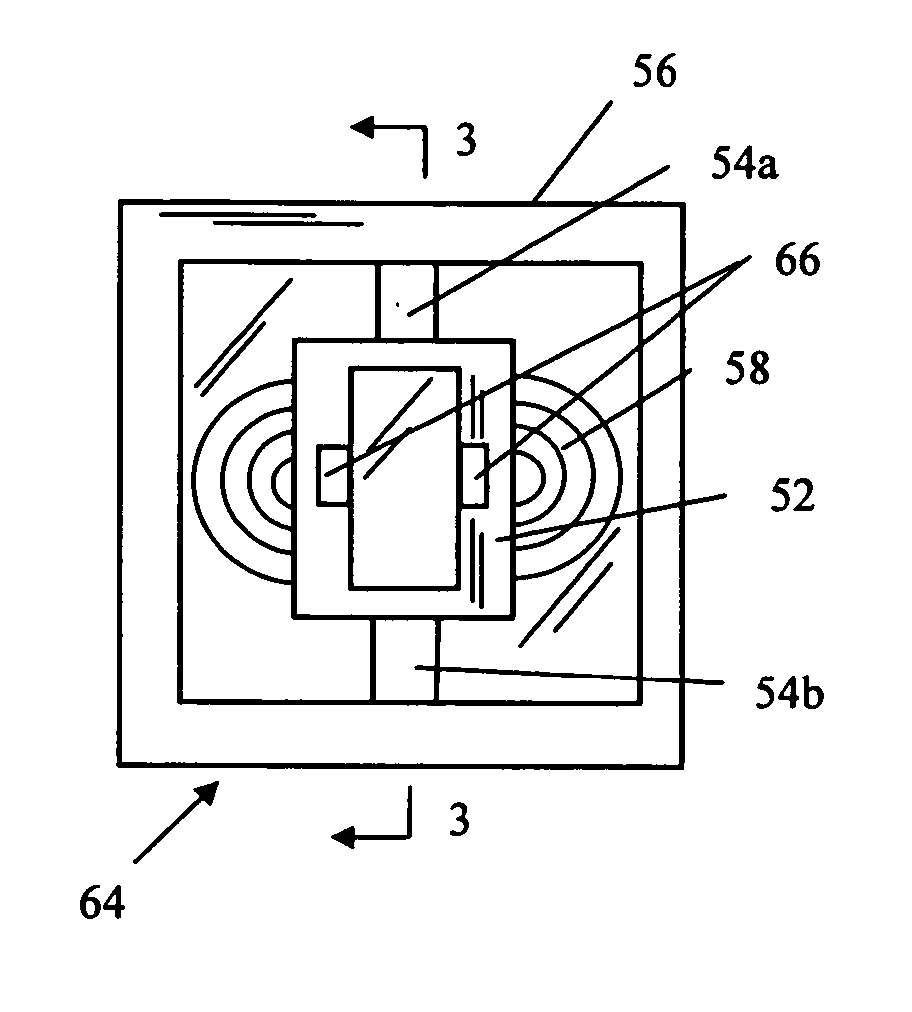
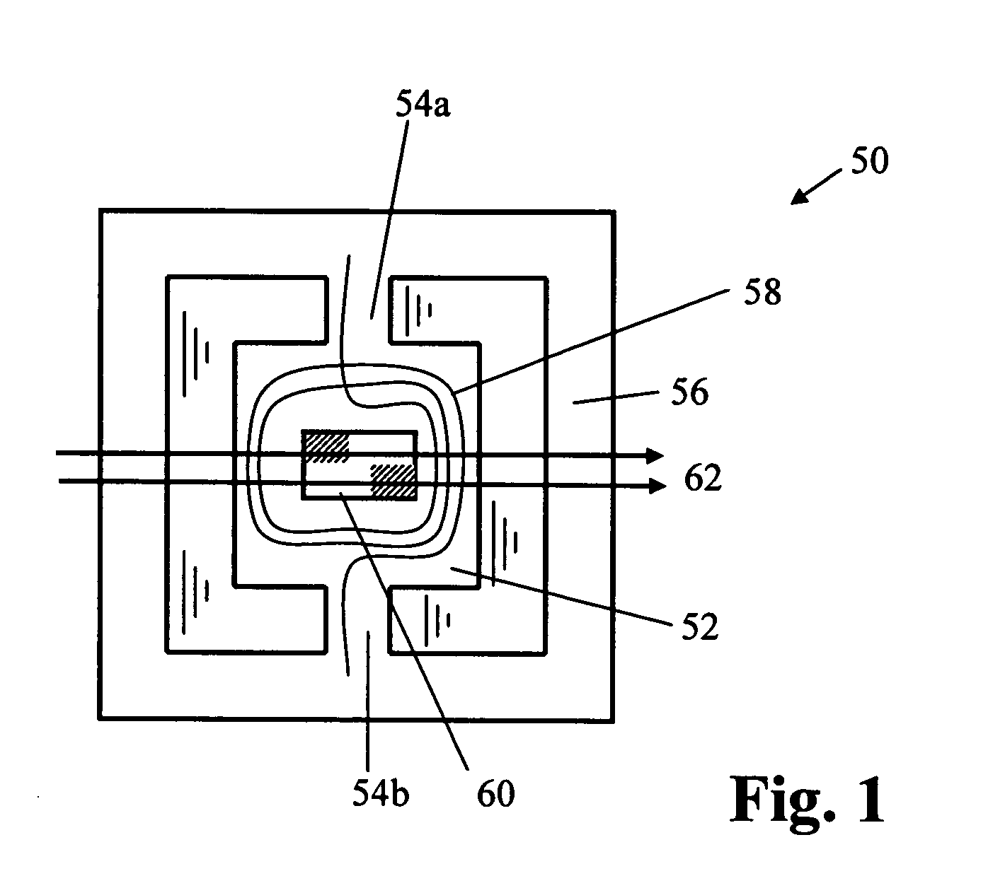
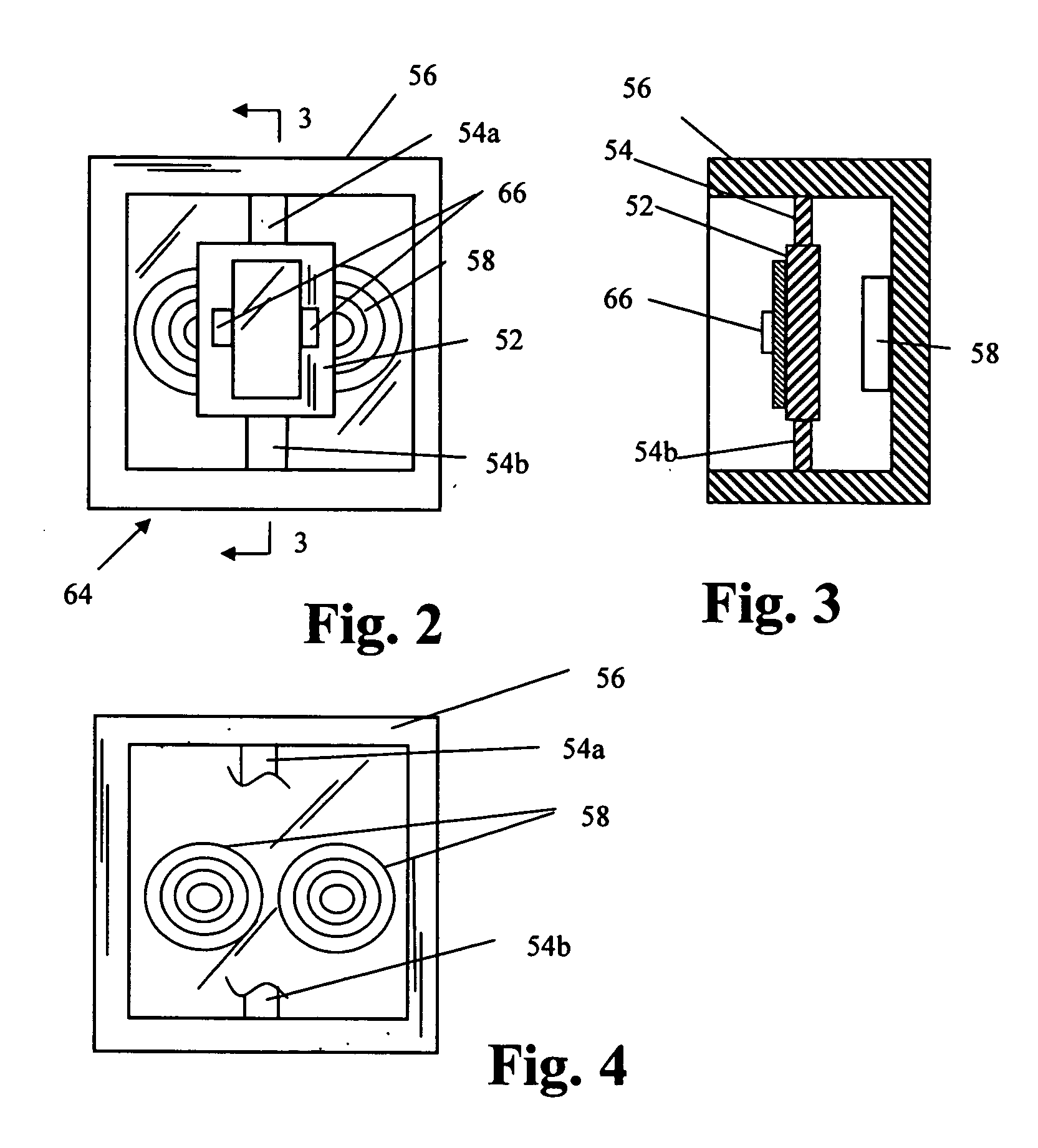
[0051] Preferred embodiments of the present invention utilize a torsion oscillator. The torsion oscillator 50 of FIG. 1 comprises a central generally rectangular plate 52 suspended by two extensions 54a, 54b of the material of plate 52. The plate 52 is generally symmetrical about its axis of oscillation. Extensions 54a, 54b are integral with a surrounding frame 56. Typically, the plate 52, extensions 54a, 54b and frame 56 are cut or etched from a single silicon wafer. A coil 58 of conductive wire and a mirror 60 or similar reflective surface are placed on the central plate. The mirror may be a smooth or polished surface on the silicon plate 52, since silicon itself is about sixty percent reflective Typically the mirror is a deposited layer of gold (or other material) on the smooth silicon substrate. Since the reflectivity of the silicon is wavelength dependent (falling off rapidly about 1 micron wavelength), a deposited mirror is typically used, or the raw silicon can be used withou...


PUM


Abstract

An image scanning apparatus and a torsion oscillator are capable of operating across a dynamic range of possible operating frequencies. The image scanning apparatus uses a light source to produce a light beam, and the oscillator scans the light beam through a scanning pattern. The oscillator includes a plate member having a non-rectangular shape. At least one magnet is disposed on the plate. A surface of the plate member includes a reflective surface for reflecting a light beam. A frame is disposed in a spaced apart relation to a lower surface of the plate member. The frame includes at least one coil configured to induce an electromagnetic force on the at least one magnet to thereby oscillate the reflective surface to a rotational angle of oscillation at an oscillation frequency. The system also includes an imaging surface disposed in the path of the scanning pattern so that the light beam scans across the imaging surface, and a mechanical drive to move the imaging surface. A control system controls electric current provided to the at least one coil to achieve the oscillation.

Description

FIELD OF THE INVENTION [0001] The present invention is generally directed to scanning systems. More particularly, the invention is directed to a stationary coil torsion oscillator scanning system. BACKGROUND OF THE INVENTION [0002] Torsion oscillators are known, although not widely employed. U.S. Pat. No. 3,803,637 to Martin et al., U.S. Pat. No. 4,762,994 to Byerly et al., U.S. Pat. No. 5,542,956 to Nakagawa et al., U.S. Pat. No. 5,543,956 to Nakagawa et al., and U.S. Pat. No. 5,767,666 to Asada et al. are illustrative. Problems associated with torsion oscillators include bulk associated with the materials used for the springs, magnets and coils; frequency drift; and instability. In general, these problems and others have prevented or discouraged use of torsion oscillators in applications such as optical systems. Current conventional wisdom provides that torsion oscillators are inferior to rotating mirror devices and are unacceptable for use in scanning devices such as commercial o...

Claims


Application Information

Patent Timeline
Patent Type & Authority Applications(United States)
IPC IPC(8): G02B26/08G02B26/10
CPCG02B26/0833G02B26/105G02B26/085
Inventor CANNON, ROGER S.GREEN, TIMOTHY A.KLEMENT, MARTIN C.PAWLEY, DANIEL E.ROUTT, WILSON M. JR.
Owner LEXMARK INT INC
Why Eureka
Try Eureka