
Apparatus and method for defining a static fibre channel fabric

a static fibre channel and fabric technology, applied in the field of storage area networks, can solve the problems of rcf and bf processes being disruptive to the fabric, affecting the data traffic in the fabric, and affecting the bf process also partially

Active Publication Date: 2009-10-20
CISCO TECH INC
View PDF13 Cites 16 Cited by
  • Summary
  • Abstract
  • Description
  • Claims
  • Application Information

AI Technical Summary

Benefits of technology

[0015]To achieve the foregoing, and in accordance with the purpose of the present invention, a storage area network and method for defining a static Fibre Channel Fabric that does not require a Principal Switch is disclosed. The storage area network comprises one or more hosts, one or more storage devices, and a static Fabric connecting the one or more hosts and storage devices. Within the static Fabric, the Switches have their Domain_ID and Fabric_Name manually set. The method comprises accessing t

Problems solved by technology

This process causes a disruption of the data traffic in the Fabric with the losing Principal Switch.
A number of problems are associated with the way Domain_IDs are assigned among the Switches of a Fabric under the current Fibre Channel standard.
Further the RCF and BF processes are disruptive to the Fabric.
The BF process is also partially disruptive.
Traffic is thus disrupted until the update is completed.
Further, Fabrics with Principal Switches are prone to catastrophic problems.
For example, if the Principal Switch goes down, it may render the entire Fabric inoperable.
Also if a cable is mistakenly plugged into the wrong connector, inadvertently connecting together two Fabrics, it may cause the entire Fabrics to be reconfigured.

Method used


Image

  • Apparatus and method for defining a static fibre channel fabric
  • Apparatus and method for defining a static fibre channel fabric
  • Apparatus and method for defining a static fibre channel fabric

Examples


Embodiment Construction

[0019]In the following description, numerous specific details are set forth in order to provide a thorough understanding of the present invention. It will be obvious, however, to one skilled in the art, that the present invention may be practiced without some or all of these specific details. In other instances, well known process steps have not been described in detail in order not to unnecessarily obscure the present invention.

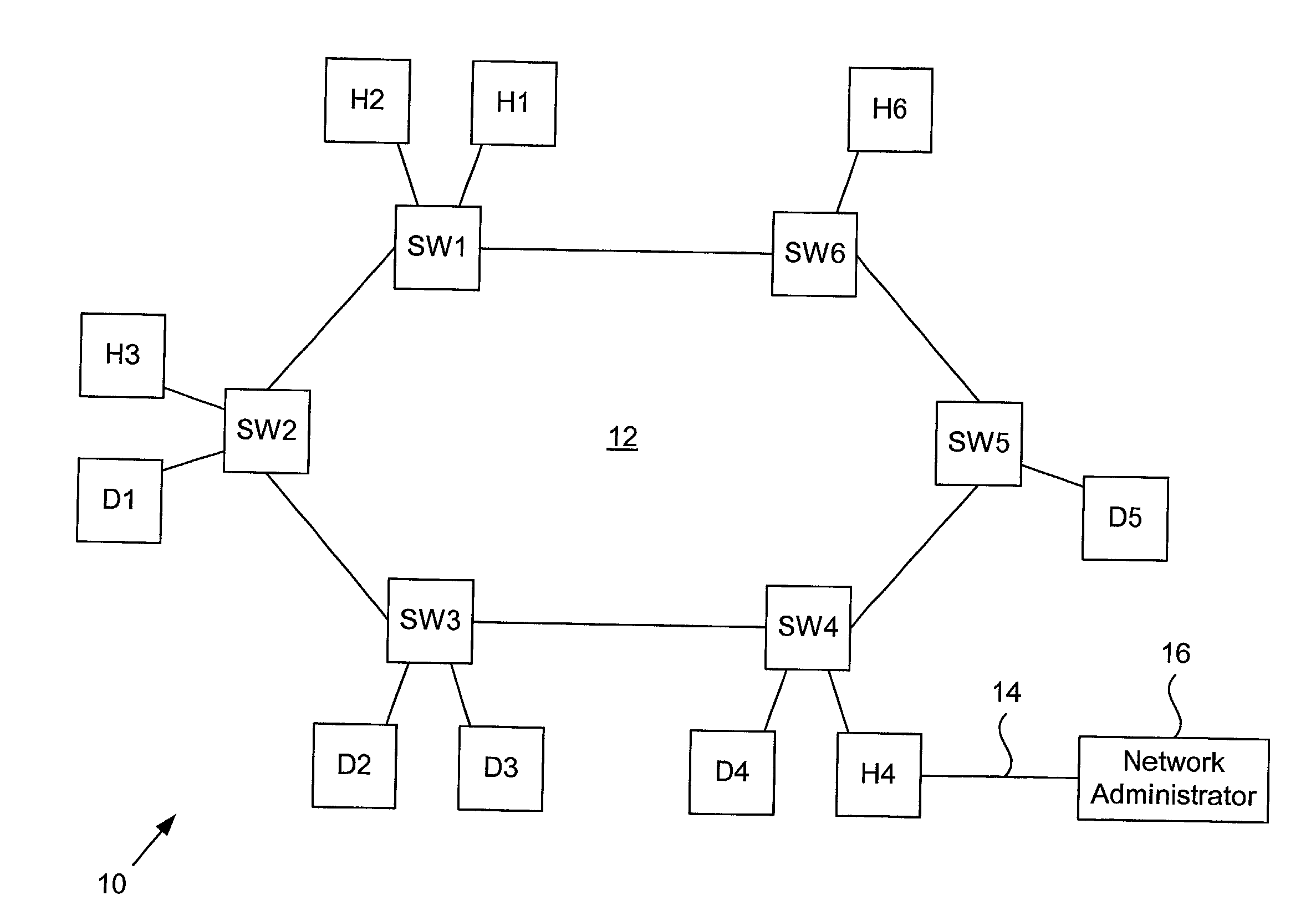
[0020]Referring to FIG. 1, a Switching Fabric of a storage area network is shown. The storage area network (SAN) 10 includes a Switching Fabric 12 that includes a plurality of Fibre Channel Switches SW1 through SW6. Also included in the SAN 10 are a plurality of hosts H1 through H6 and a plurality of storage devices D1 through D5. A tool to manage the Fabric, such as a command line interpreter or a graphic management application 14, is connected to the Fabric 12 through the host H4. The command line interpreter or management application 14 enables a network ...


PUM


Abstract

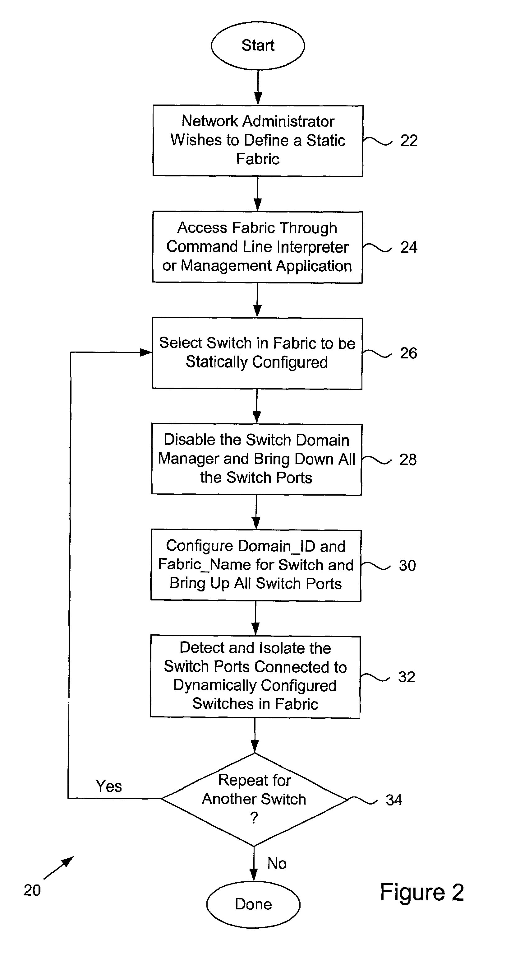
A storage area network and method for defining a static Fibre Channel Fabric that does not require a Principal Switch. The storage area network comprises one or more hosts, one or more storage devices, and a static Fabric connecting the one or more hosts and storage devices. Within the static Fabric, the Switches have their Domain_ID and Fabric_Name statically set. The method comprises accessing the Fabric, selecting a Switch in the Fabric, and statically configuring the Domain_ID and Fabric_Name for the selected Switch. The above sequence is repeated for each Switch in the static Fabric. In one embodiment, after being statically configured, the Switch is isolated from any dynamically set Switches in the Fabric. The Switch detects which of its Ports are connected to dynamically set Switches, and then isolates them, while maintaining operational the Ports connected to statically configured Switches.

Description

BACKGROUND OF THE INVENTION[0001]1. Field of the Invention[0002]The present invention relates to storage area networks, and more particularly, to an apparatus and method for defining a static Fibre Channel Fabric which does not require a Principal Switch.[0003]2. Background of the Invention[0004]With the increasing popularity of Internet commerce and network centric computing, businesses and other organizations are becoming more and more reliant on information. To handle all of this data, storage area networks or SANs have become very popular. A SAN typically includes a number of storage devices, a number of hosts, and a plurality of Switches arranged in a Switching Fabric. The Switches selectively connect the storage devices and the hosts within the SAN.[0005]Most SANs rely on the Fibre Channel protocol for communication within the Fabric. For a detailed explanation of the Fibre Channel protocol and Fibre Channel Switching Fabrics, see FC-FS (Fibre Channel Framing and Signaling ) a...

Claims


Application Information

Patent Timeline
IPC IPC(8): H04L12/28G06F13/10G06F13/14H04L12/24H04L12/56
CPCH04L12/24H04L41/00H04L45/00H04L41/0879H04L41/0803G06F12/08G06F9/46H04L45/036
Inventor DESANTI, CLAUDIODI BENEDETTO, MARCO
Owner CISCO TECH INC
Learn More