Isolation switch for fibre channel fabrics in storage area networks

a technology of isolation switch and fibre channel fabric, which is applied in the direction of transmission, hardware monitoring, and unauthorized memory use protection, can solve the problems of production data disruption, cpus of constituent switch to get overloaded, and the scaling of dynamic fibre channel fabric is a challenging problem, so as to promote scalability within the enterprise fabric and increase interoperability

Active Publication Date: 2005-09-08
AVAGO TECH INT SALES PTE LTD
View PDF34 Cites 169 Cited by
  • Summary
  • Abstract
  • Description
  • Claims
  • Application Information

AI Technical Summary

Benefits of technology

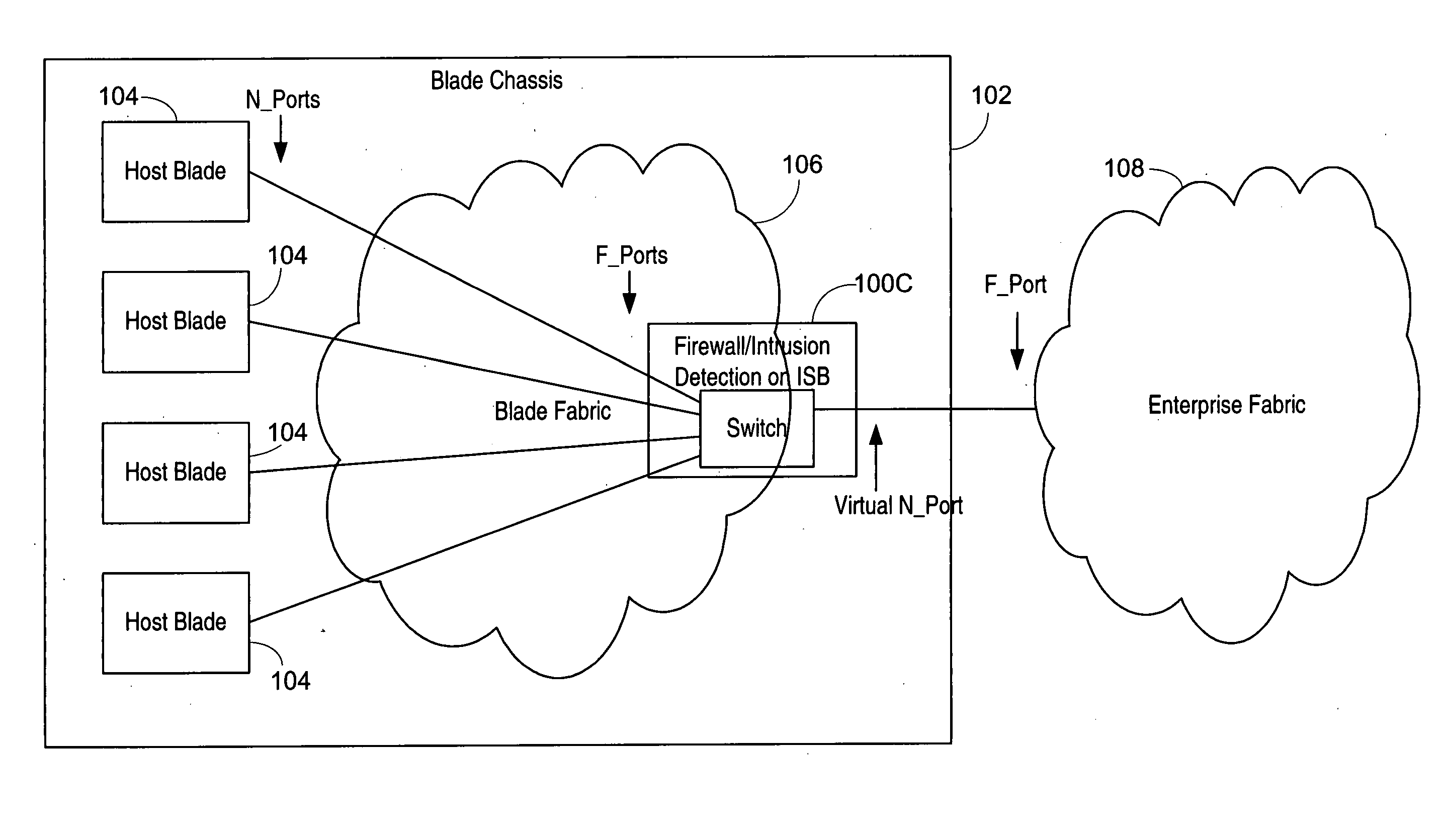
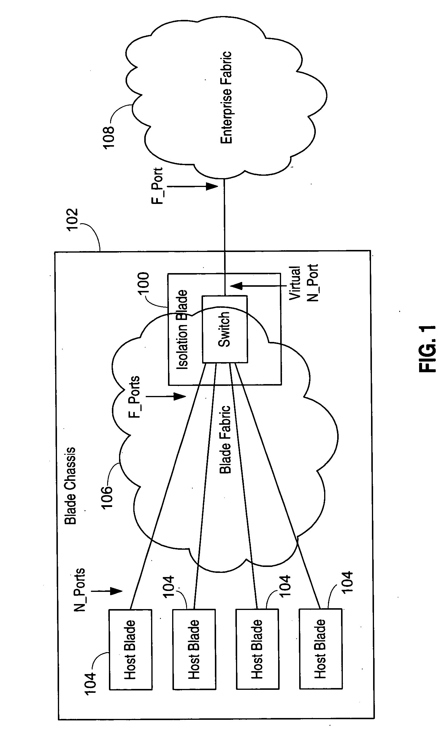
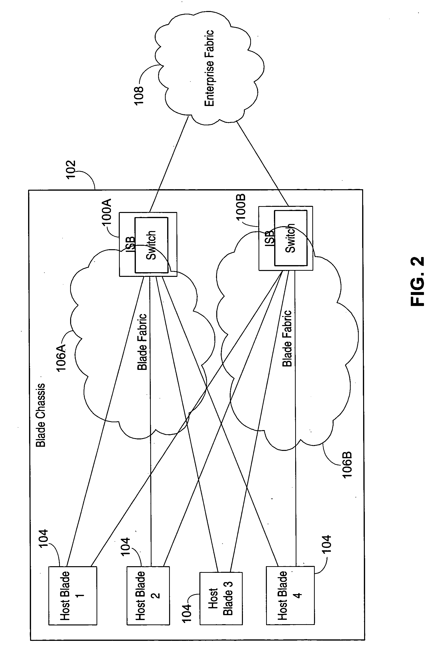
[0007] The use of N_port virtualization also enables the isolation switch blade to act as an initiator, which is advantageous as this allows partitioning of fabrics and isolation of the enterprise fabric from exchanges originating from the host processor blades. Since the host processor blades are not directly connected to the enterprise fabric, the enterprise fabric is isolated from large amounts of fabric activity due to host processor blades being swapped in and out. This isolation promotes scalability within the enterprise fabric. Since the isolation switch blade may preferably be a single conduit into the enterprise fabric, it is also a good point to enforce perimeter defenses (similar to a firewall) against attacks, either intentional or resulting from misbehaviors. The isolation switch blade may also act as a throttle by controlling the host processor blade access into the enterprise fabric. Further, the isolation switch blade may act as a protocol gateway. In addition, the use of the N_port connection increases interoperability, as compared to using an E_port connection.

Problems solved by technology

The scaling of dynamic Fibre Channel fabrics is a challenging problem.
When switches are added to or removed from a fabric they tend to precipitate high volumes of control traffic, causing the CPUs of the constituent switches to get overloaded, and often result in production data disruption due to fabric re-configurations.
Fabrics also tend to become unstable while handling large volumes of fabric events.
The hot-plug capabilities of these, possibly large, numbers of host and switch blades increases the probability of “event storms,” resulting in loading or disrupting the enterprise fabrics they are connected to.
These problems may ultimately result in loss of service (e.g., host bus adapter logins may timeout) under heavy load conditions in the fabric.

Method used


Image

  • Isolation switch for fibre channel fabrics in storage area networks
  • Isolation switch for fibre channel fabrics in storage area networks
  • Isolation switch for fibre channel fabrics in storage area networks

Examples


Embodiment Construction

[0023] Many organizations have begun consolidating their file servers into centralized data centers, looking to use physical, application or data consolidation as a means of reducing the challenges and costs associated with administering many small file servers scattered across the enterprise. To date, physical consolidation has generally involved replacing bulky tower servers with slender 1U or 2U rack systems. Such rack systems take less space and put the servers and infrastructure within easy reach of the network administrator, rather than spread across a large area.

[0024] These servers enable organizations to reap many benefits of consolidation, yet because each server requires its own infrastructure—including, e.g., cables for power, Ethernet, systems management, power distribution units (PDUs), keyboard / video / mouse (KVM) switches and Fibre Channel switches—they present challenges of their own. A rack of 1U servers can have hundreds of cables strung throughout the rack, making...


PUM


Abstract

An isolation switch blade Fibre Channel switch presents F_ports to form a first Fibre Channel fabric and N_ports to a second Fibre Channel fabric to appear as node devices. The isolation switch blade may be used to connect a plurality of blade servers to a Fibre Channel fabric. Fabric events engendered by the insertion or removal of hot-pluggable devices are handled by the isolation switch blade and “event storms” on the Fibre Channel fabric are avoided. The isolation switch blade presents the blade servers to the FC fabric as a virtualized N_port.

Description

BACKGROUND OF THE INVENTION [0001] 1. Field of the Invention [0002] This invention relates to storage area networking using the Fibre Channel protocol. More particularly, it relates to storage area networks connected to blade-type file servers. [0003] 2. Description of the Related Art [0004] The scaling of dynamic Fibre Channel fabrics is a challenging problem. When switches are added to or removed from a fabric they tend to precipitate high volumes of control traffic, causing the CPUs of the constituent switches to get overloaded, and often result in production data disruption due to fabric re-configurations. Fabrics also tend to become unstable while handling large volumes of fabric events. These issues are further exacerbated by the growing trend to blade servers. The host processor blades in the blade servers are intended to be hot-pluggable. Further, any Fibre Channel switch located on a blade would also be intended to be hot-pluggable. This makes fabrics even more dynamic and ...

Claims


Application Information

Patent Timeline
Patent Type & Authority Applications(United States)
IPC IPC(8): G06F11/30
CPCH04L49/3009H04L49/356H04L49/357H04L67/1097H04L49/55H04L49/70H04L63/0227H04L49/50
Inventor SHANBHAG, SANTOSHHAMMONS, RICHARD L.KAUSHIK, BALAKUMAR N.GUAN, VINCENT W.
Owner AVAGO TECH INT SALES PTE LTD
Why Eureka
Try Eureka