Dead cable end

a dead cable and end technology, applied in the direction of cable termination, cable junction, cable connection, etc., can solve the problems of difficult to tighten the dead cable end assembly, damage to the cable, and damage to the light weight core of the dead cable, so as to prevent internal rotation during tightening and reduce or eliminate the damage to the cable

Inactive Publication Date: 2009-10-27
BYRNE JOSEPH +1
View PDF12 Cites 8 Cited by
  • Summary
  • Abstract
  • Description
  • Claims
  • Application Information

AI Technical Summary

Benefits of technology

[0004]The present invention addresses the above and other needs by providing a dead cable end which distributes holding force over a length of a cable end to reduce or eliminate damage to cables. The dead cable end includes a housing containing a plurality of collets each residing in a collet receptacle. Each collet includes a conical exterior and a lengthwise collet gap, and each collet receptacle includes a conical interior. The collets and collet receptacle are held inside the housing by a screw-in retaining nut, and the collet and collet receptacle pairs are compressed between the retaining nut and a spring inside the housing. The cable end resides inside the collets, and axial compressive forces on each collet and collet receptacle pair cause each collet to compress radially and hold the cable end. Anti-rotation pins are inserted through the housing into slots in the collet receptacle next to the screw-in retainer to prevent internal rotation during tightening.

Problems solved by technology

Such light weight cores may be damaged by cable ends which concentrate holding forces over a small area of the cable surface.
While the dead cable end assembly of the '746 patent provides a solution in most instances, in some instances it is difficult to tighten the dead cable end assembly without twisting the cable inside the dead cable end assembly and thereby damage the cable.

Method used


Image

  • Dead cable end
  • Dead cable end
  • Dead cable end

Examples


Embodiment Construction

[0049]The following description is of the best mode presently contemplated for carrying out the invention. This description is not to be taken in a limiting sense, but is made merely for the purpose of describing one or more preferred embodiments of the invention. The scope of the invention should be determined with reference to the claims.

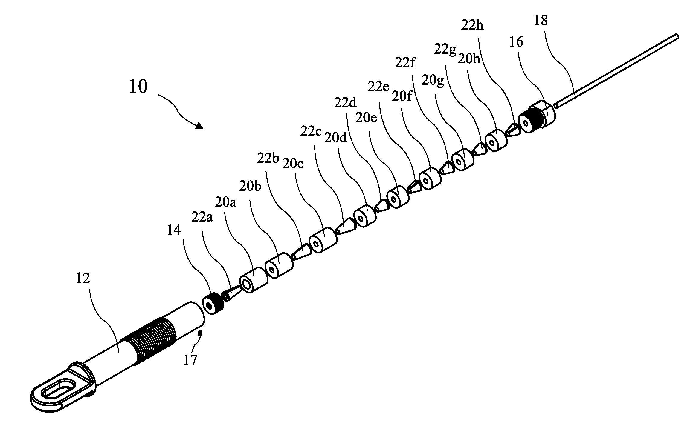
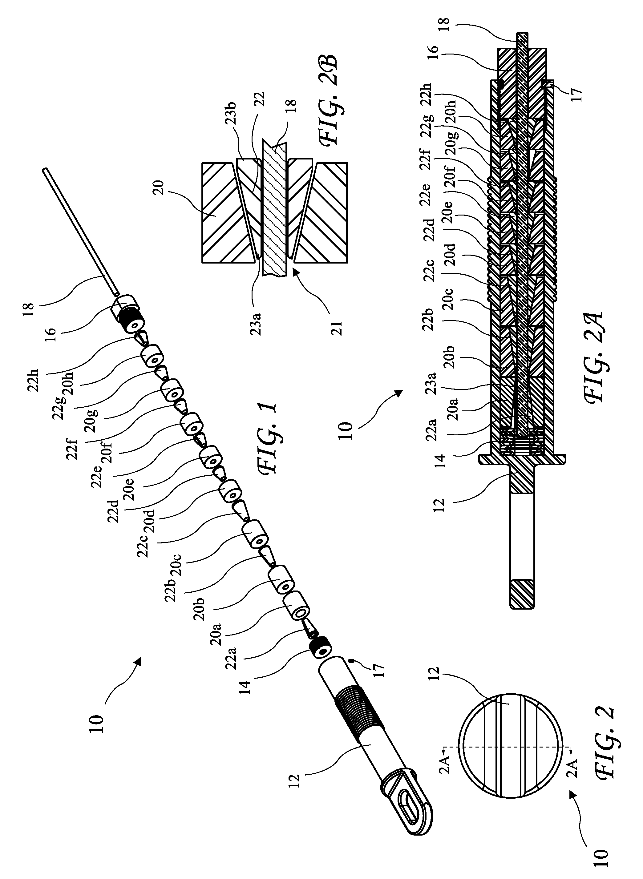
[0050]An exploded view of a dead cable end assembly 10 according to the present invention for securing a cable 18 is shown in FIG. 1. An end view of the dead cable end assembly 10 is shown in FIG. 2, a cross-sectional view of the dead cable end assembly 10 taken along line 2A-2A of FIG. 2 is shown in FIG. 2A, and a detailed view of a general collet 22 and collet receptacle 20 is shown in FIG. 2B. The dead cable end assembly 10 secures the cable 18 through a multiplicity of collets 22a-22h cooperating with a multiplicity of collet receptacles 20a-20h. The collets 22a-22h and the collet receptacles 20a-20h are contained in a dead cable end assembly ...


PUM


Abstract

A dead cable end distributes holding force over a length of a cable end to reduce or eliminate damage to cables. The dead cable end includes a housing containing a plurality of collets each residing in a collet receptacle. Each collet includes a conical exterior and a lengthwise collet gap, and each collet receptacle includes a conical interior. The collets and collet receptacle are held inside the housing by a screw-in retaining nut, and the collet and collet receptacle pairs are compressed between the retaining nut and a spring inside the housing. The cable end resides inside the collets, and axial compressive forces on each collet and collet receptacle pair cause each collet to compress radially and hold the cable end. Anti-rotation pins are inserted through the housing into slots in the collet receptacle next to the screw-in retainer to prevent internal rotation during tightening.

Description

[0001]The present application is a Continuation in Part of U.S. patent application Ser. No. 11 / 712,746 filed Feb. 27, 2007 which claims the benefit of U.S. Provisional Application Ser. No. 60 / 777,692, filed Feb. 27, 2006, which applications are incorporated in their entirety herein by reference.BACKGROUND OF THE INVENTION[0002]The present invention relates to securing the ends of cables and in particular to force distributing ends for securing the ends of cables.[0003]Light weight cables have been developed which replace heavy steel cores with light weight cores, such as a carbon fiber core with a fiberglass sheath. Such light weight cores may be damaged by cable ends which concentrate holding forces over a small area of the cable surface. U.S. patent application Ser. No. 11 / 712,746 filed Feb. 27, 2007 by the present applicant describes a dead cable end assembly having a series of collets and collet receptacles which distribute the holding forces over a length of the cable to preven...

Claims


Application Information

Patent Timeline
Patent Type & Authority Patents(United States)
IPC IPC(8): H01R11/09
CPCH01R13/5804H02G7/056H01R13/585
Inventor BYRNE, JOSEPHFORSTER, MARK A.
Owner BYRNE JOSEPH
Why Eureka
Try Eureka